|
LA6NCA
RADIO COLLECTION |
|
|
LA6NCA
RADIO COLLECTION |
|
| For
full resolution of the images you can click twice on
them. |
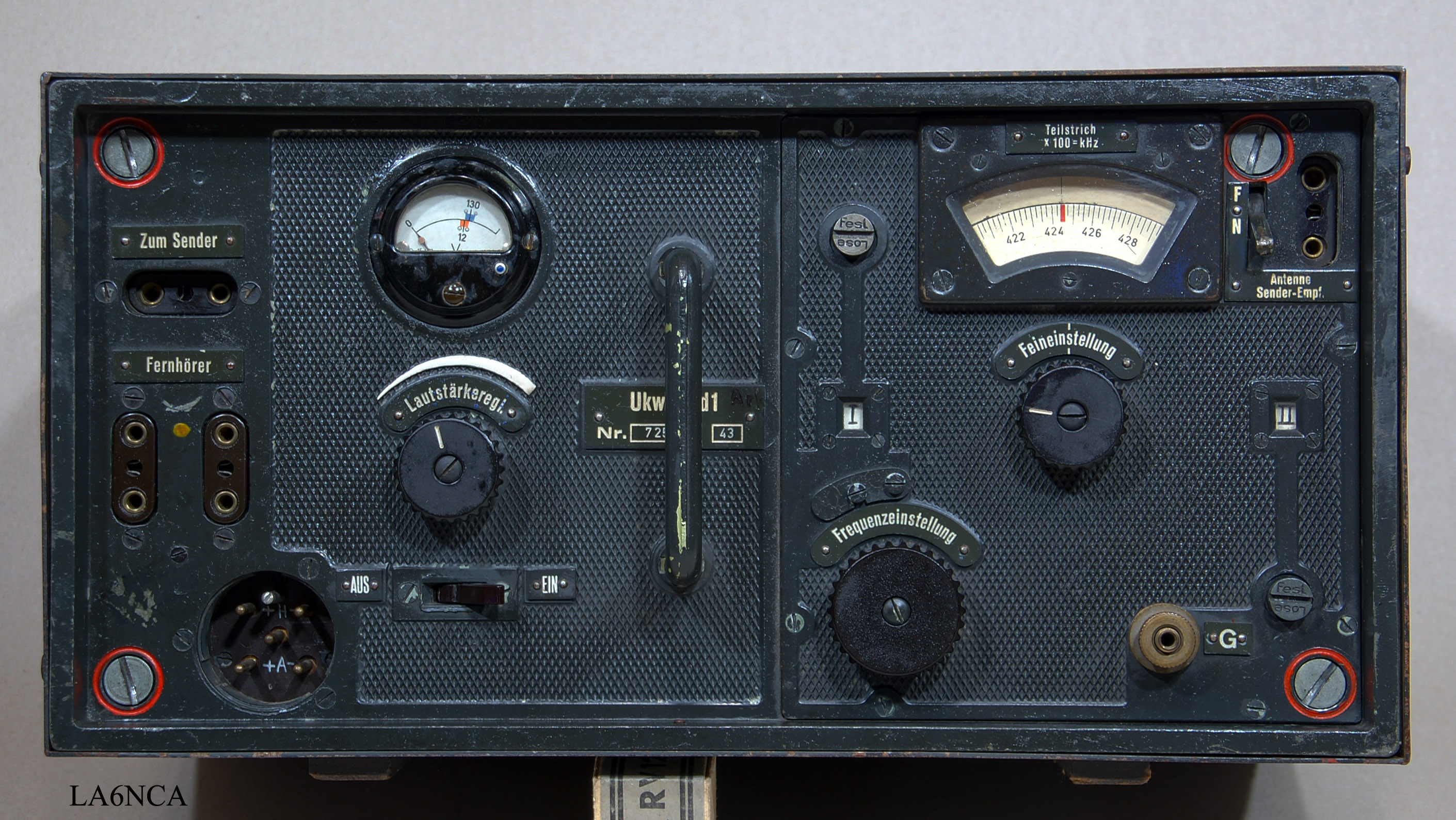
| This is a VHF
receiver for use in armored vehicles for communications
with aircraft. It uses the frequency range 42.1 to 47.8 MHz. The transmitter is 20W.S.d. |
| This is one of the
finest designed German WW2 radios I've worked with. The mechanical design is fantastic. So is also the electrical performance. On this page I use the word "amazing" and "fantastic" many times. It is entirely legitimate for this receiver is amazing. |
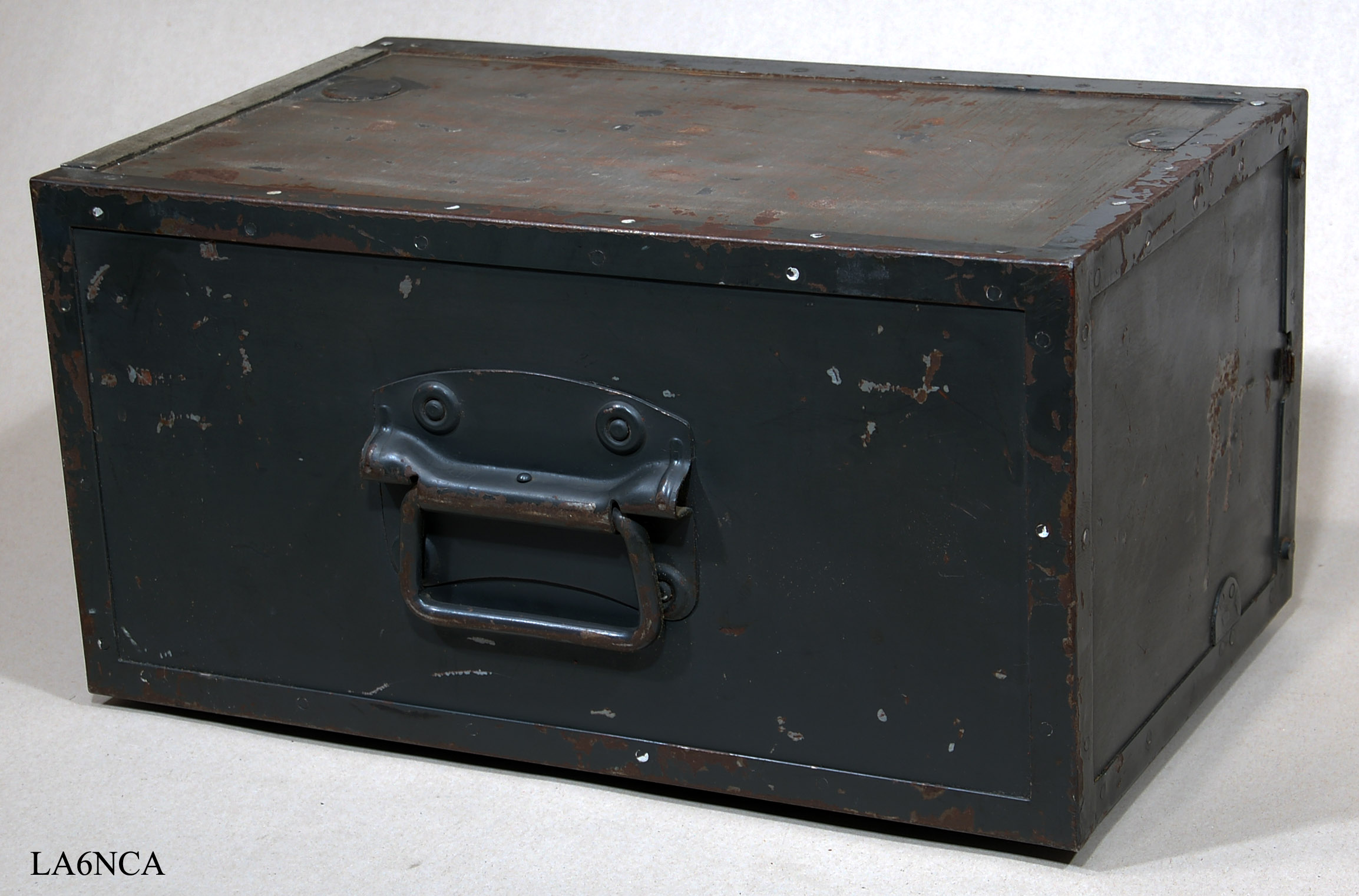
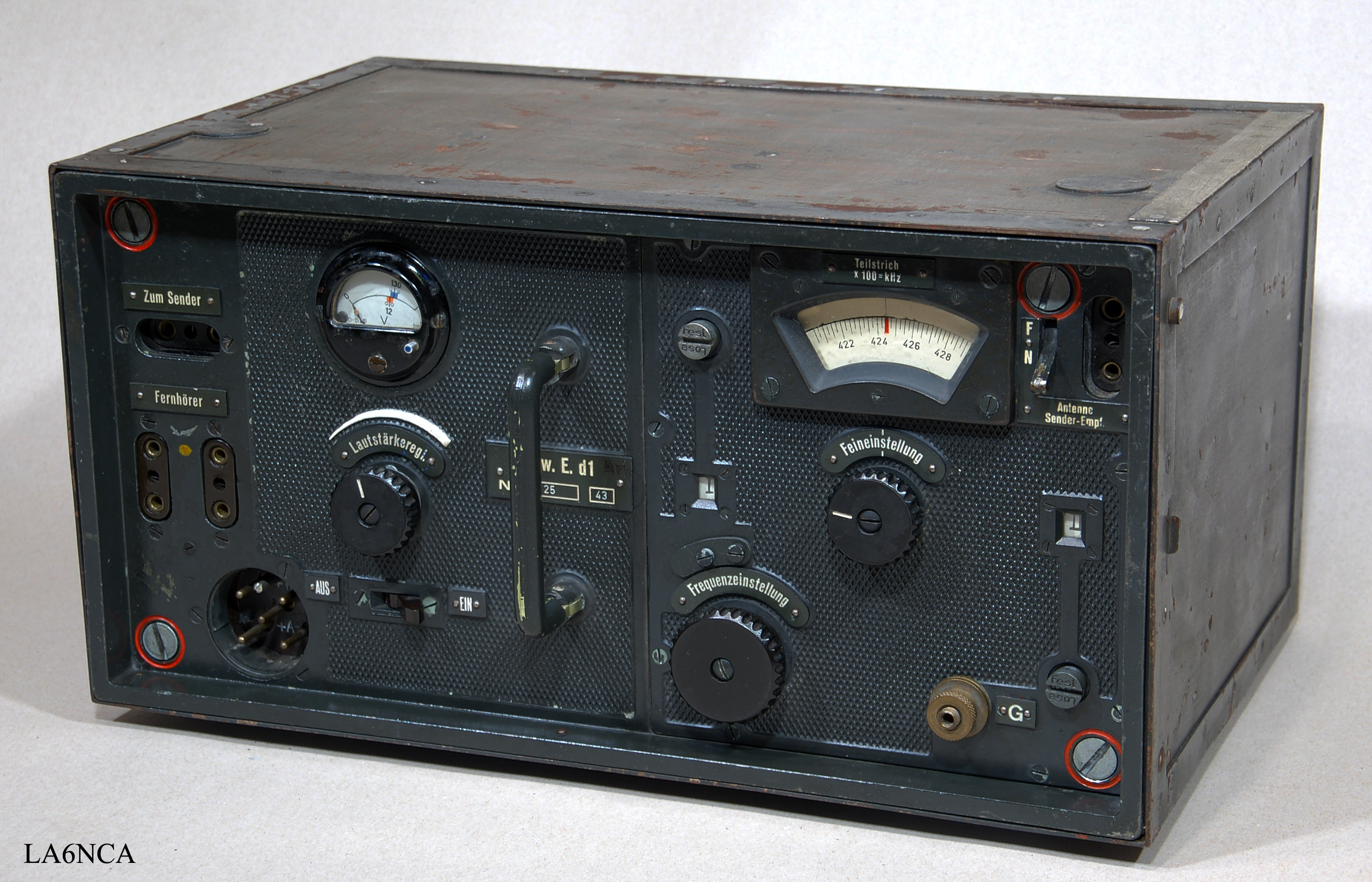
U22a
On the back of the radio
is a practical carrying handle.
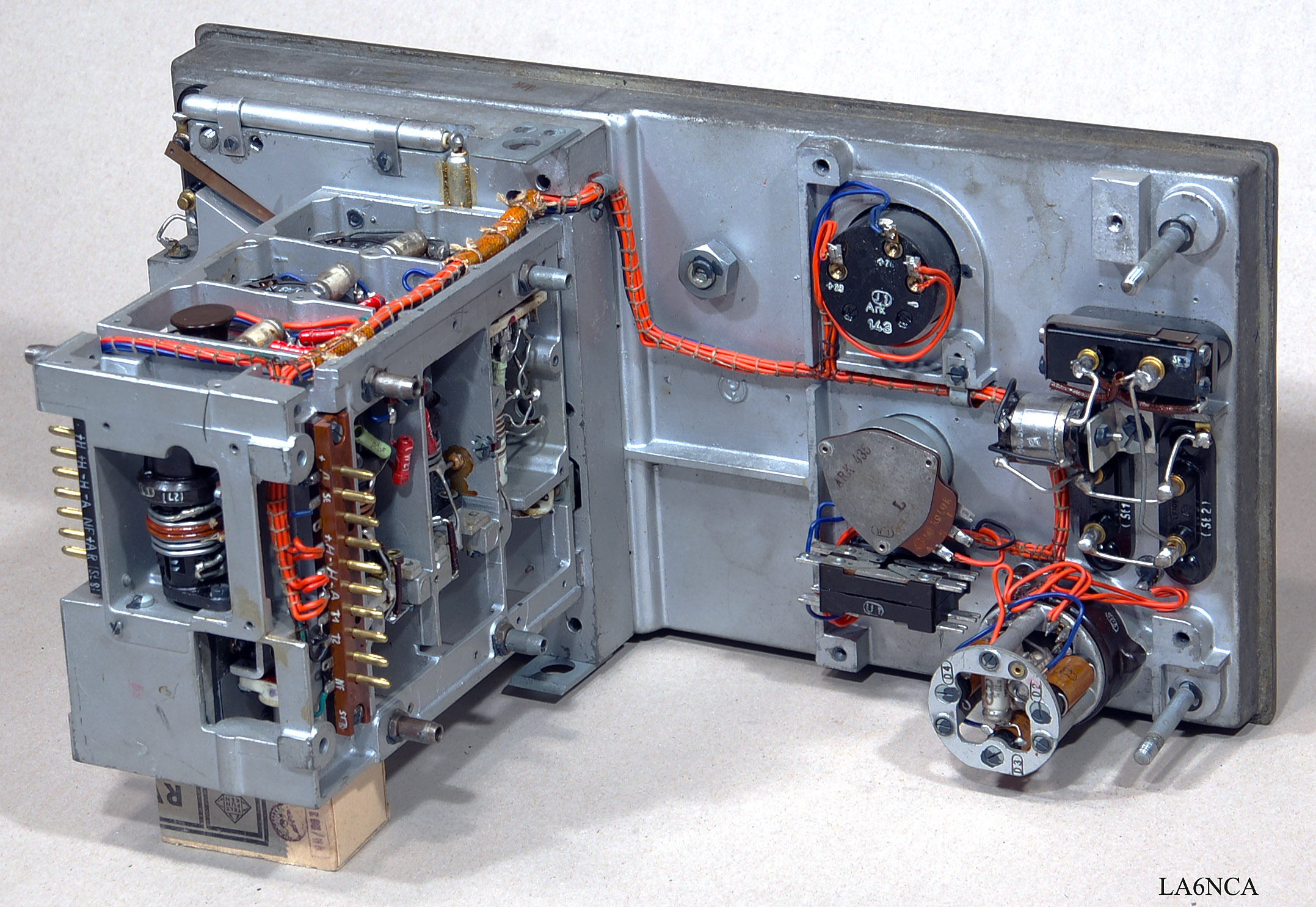
U2a
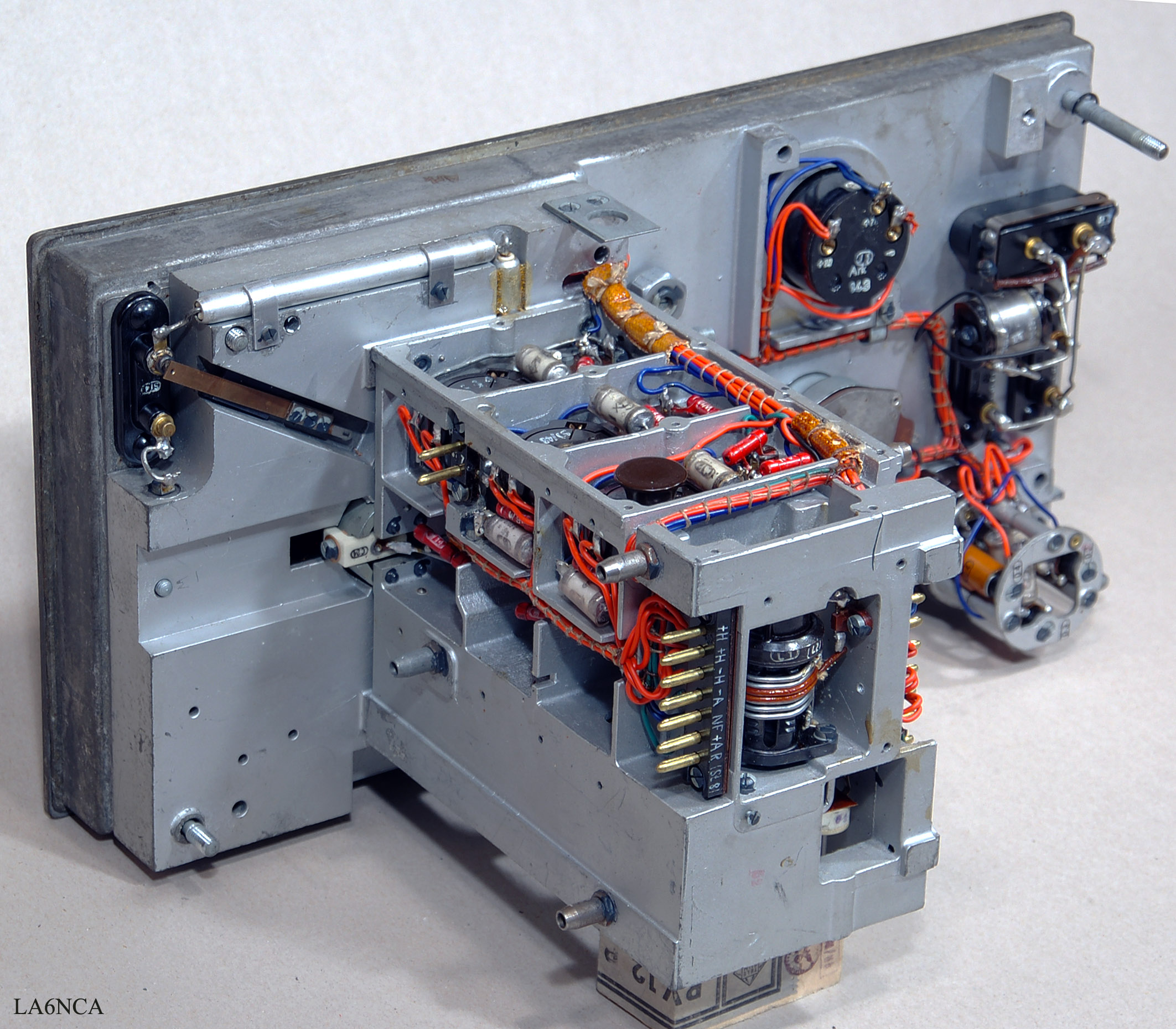
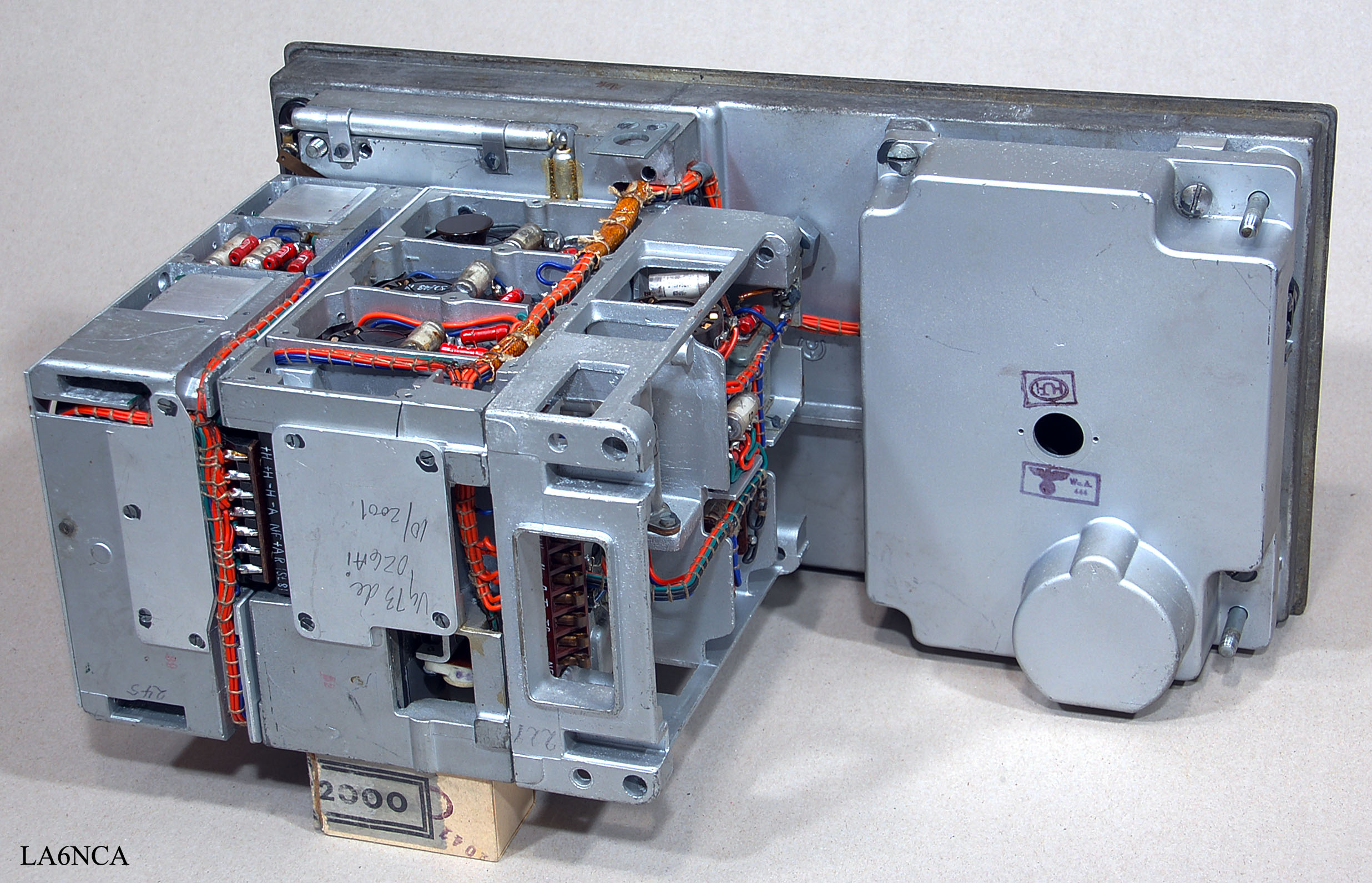
| Here you can see the amazing
construction of the receiver. The receiver consists of three main parts. From left: MF amplifier, RF part and Audio Amplifier. To the right we have a cover that Shielded connectors and instrument. |
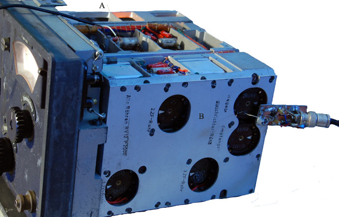
| I have here removed
MF section and audio amplifier. Also removed Shielded covers on RF section. |
| RF section consists
of three parts. From the front we OSILLATOR, MIXER and RF amplifier. |
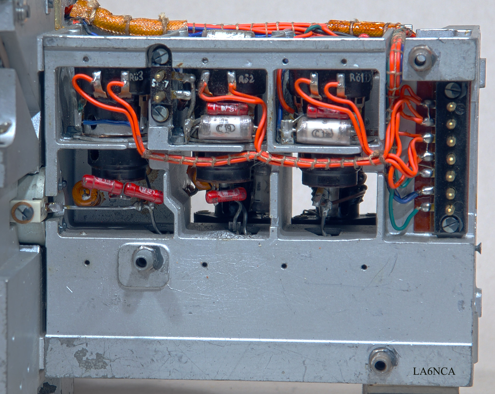
| The three tubes in
the RF section From the left we have OSILLATOR, MIXER and RF amplifier tubes. See how the cables are tied together. Great work. |
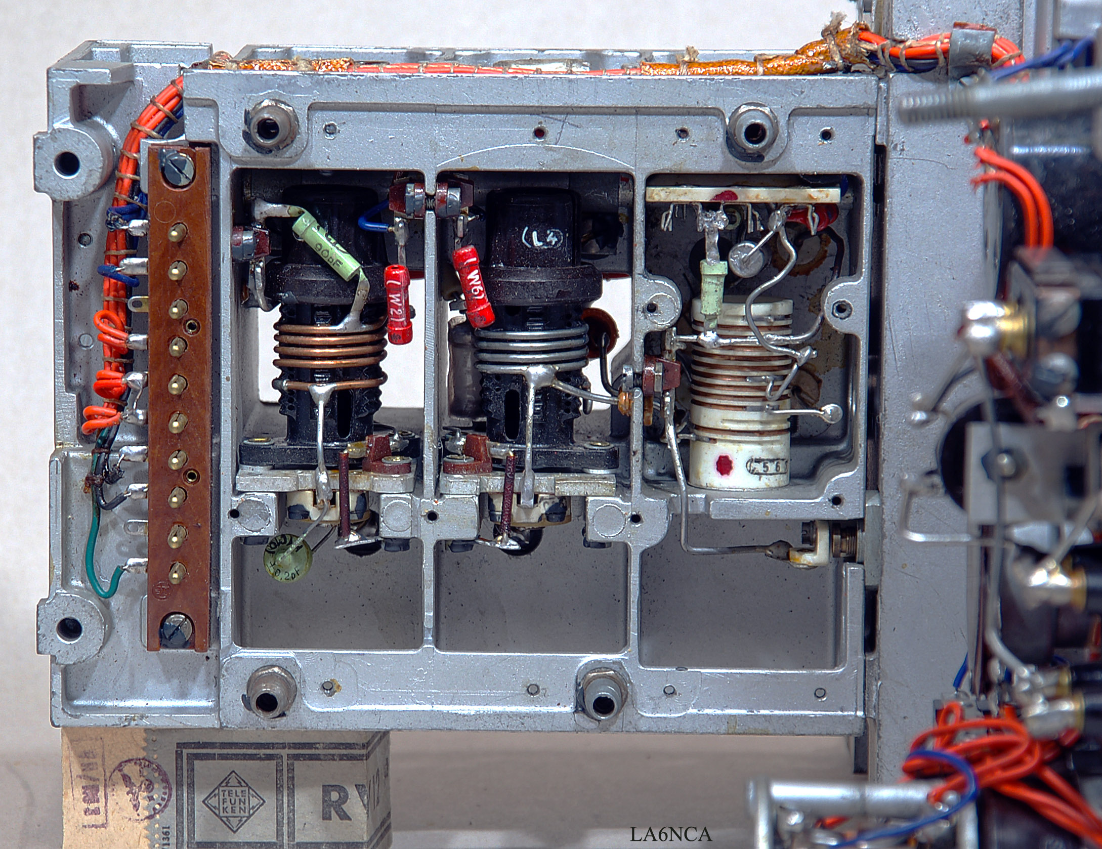
| Here are the coils
in the RF section. Oscillator has a fantastic ceramic coil. It is these components that make frequency stability so amazing. Notice the amazing casting technique used here. |
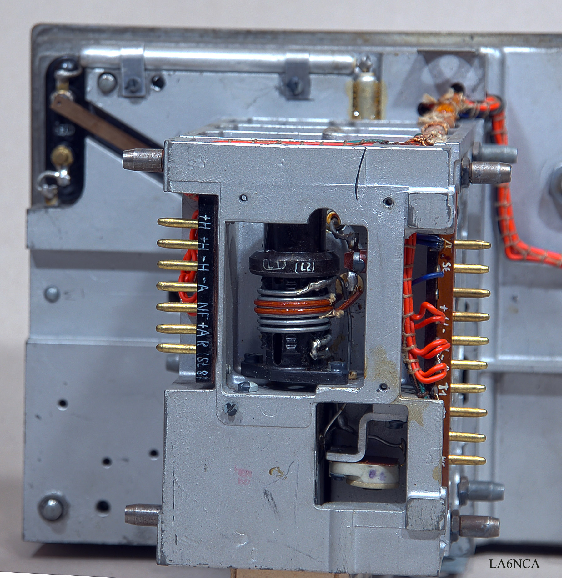
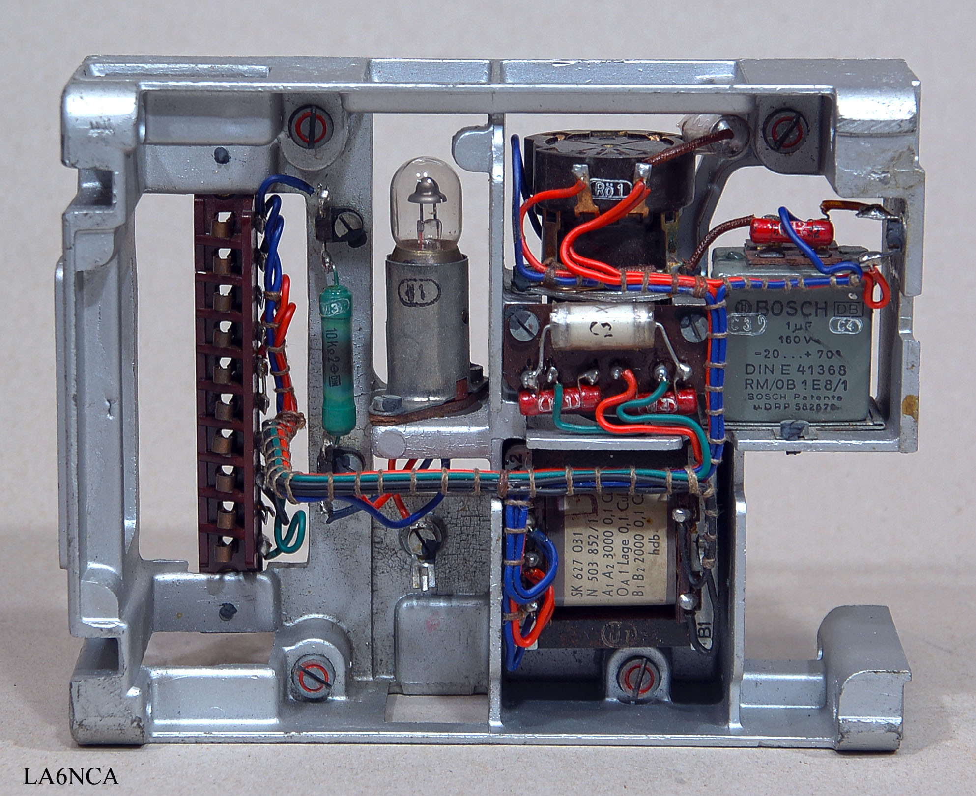
| Audio amplifier. Great casting technique and wiring here too. |
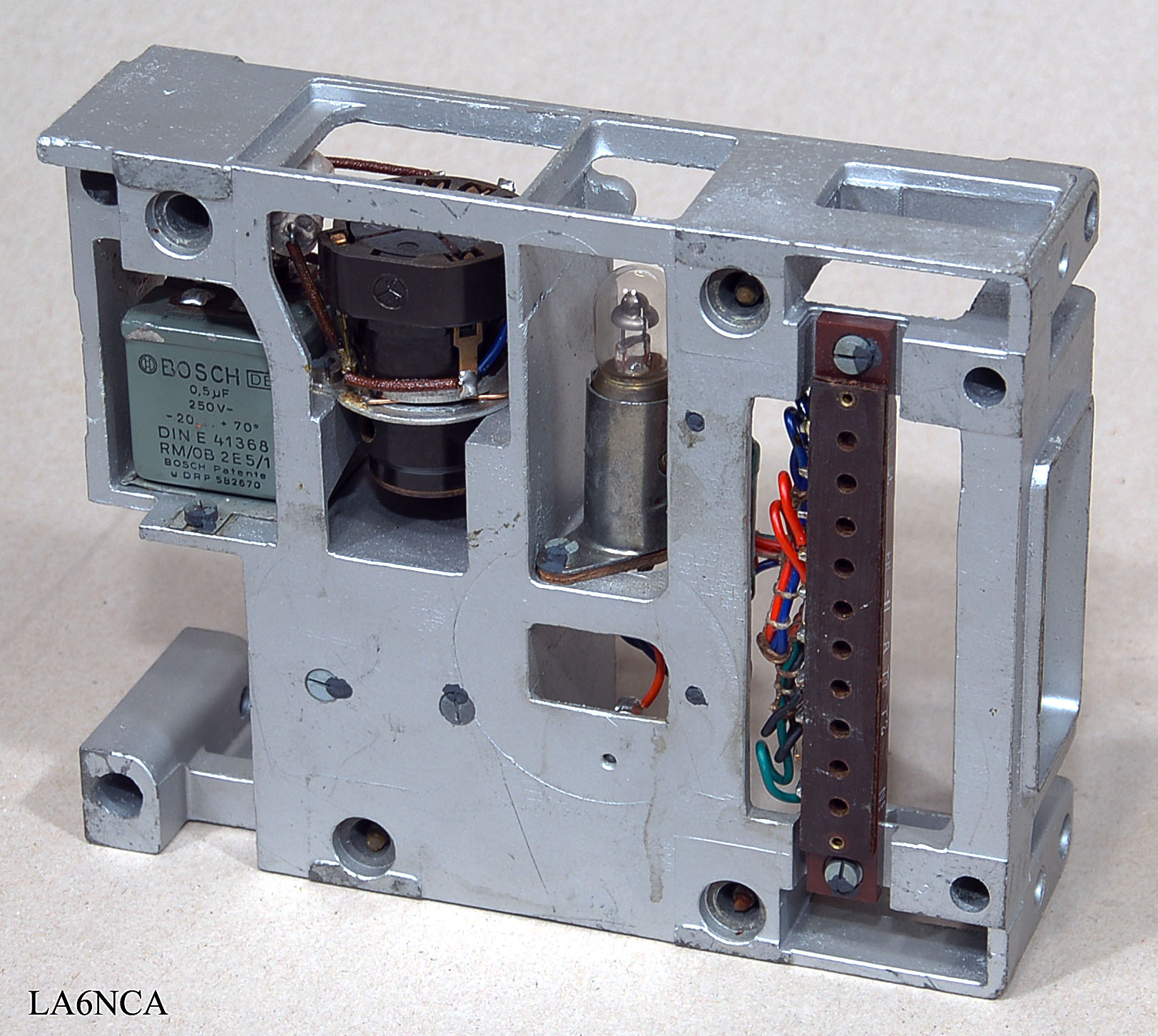
U4a
The back of the
audio amplifier.
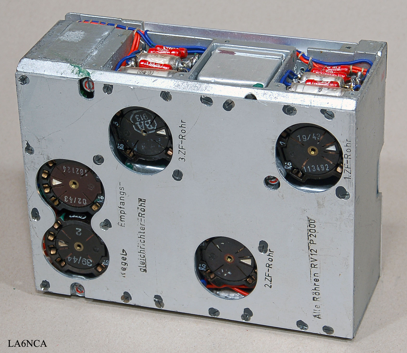
U5a
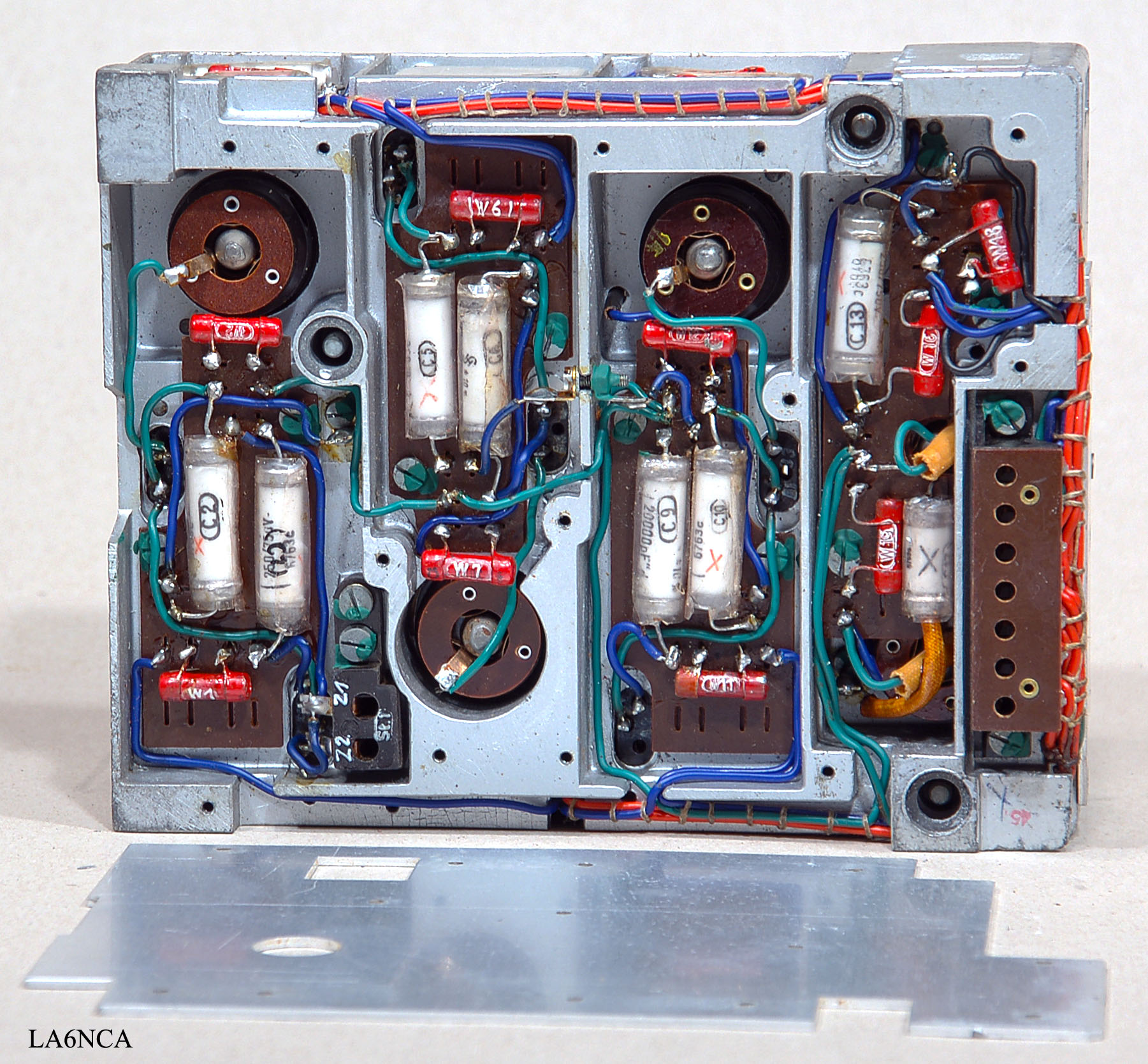
Here is the amazing
MF filter with 5 tubes
U6a
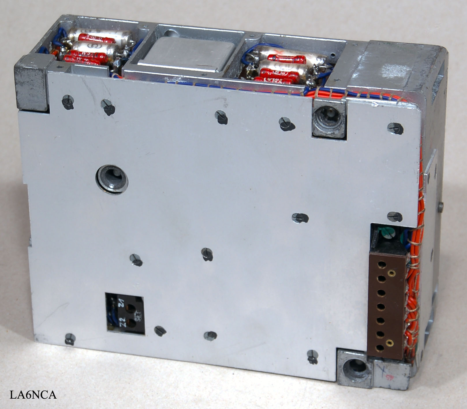
The back of the MF
filter. Here are the contacts that plugs into the RF section.
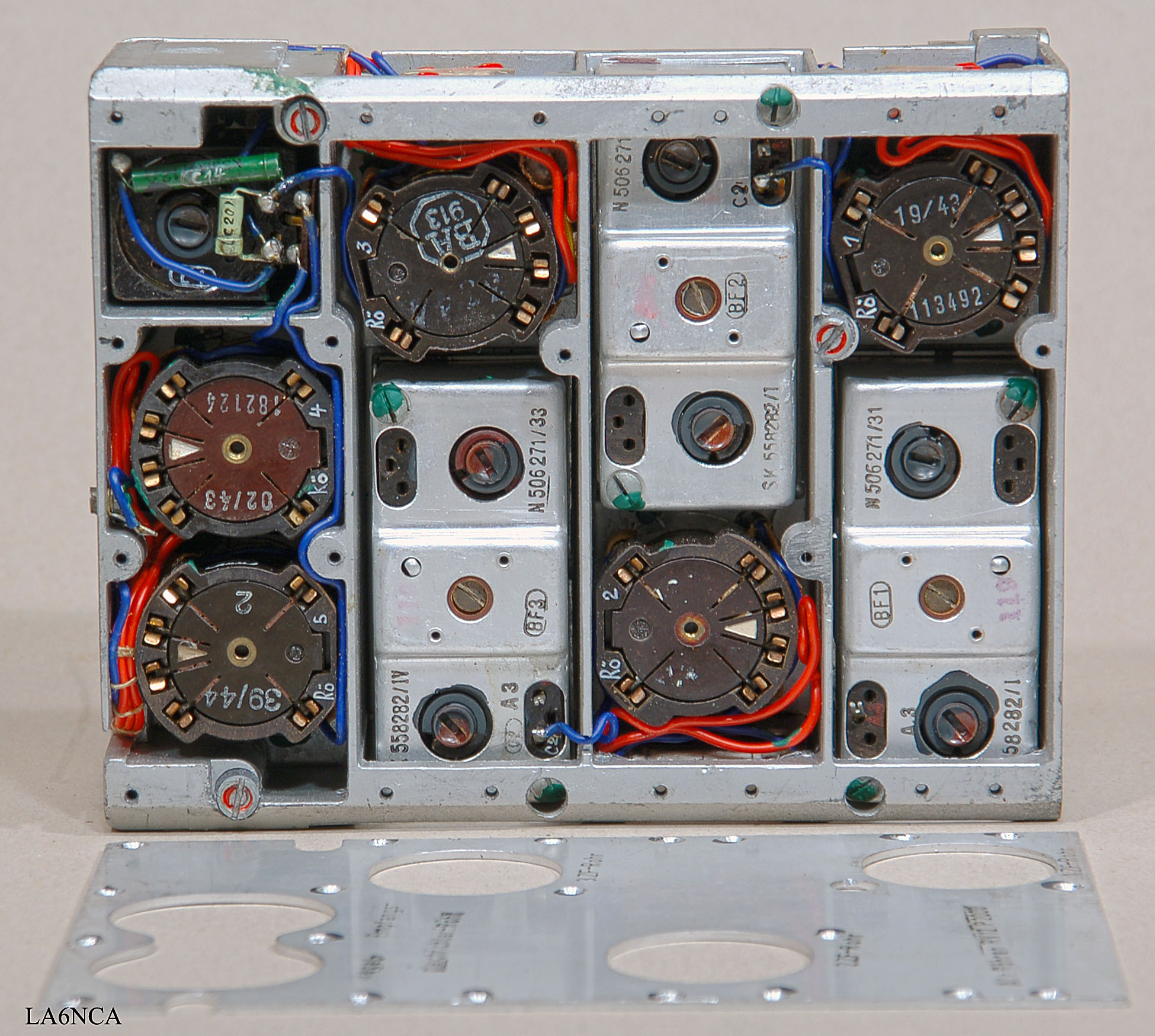
U7a
| Here's MF filter. This is designed just fantastic. This is some of the best German WW2 radio design. Click twice on the image and study the details. View test result below. |
| The back of the MF filter. The casting of metal is matched to each component. Here we have a perfect shielding of the signals. |
MEASUREMENT
RESULTS
U9a
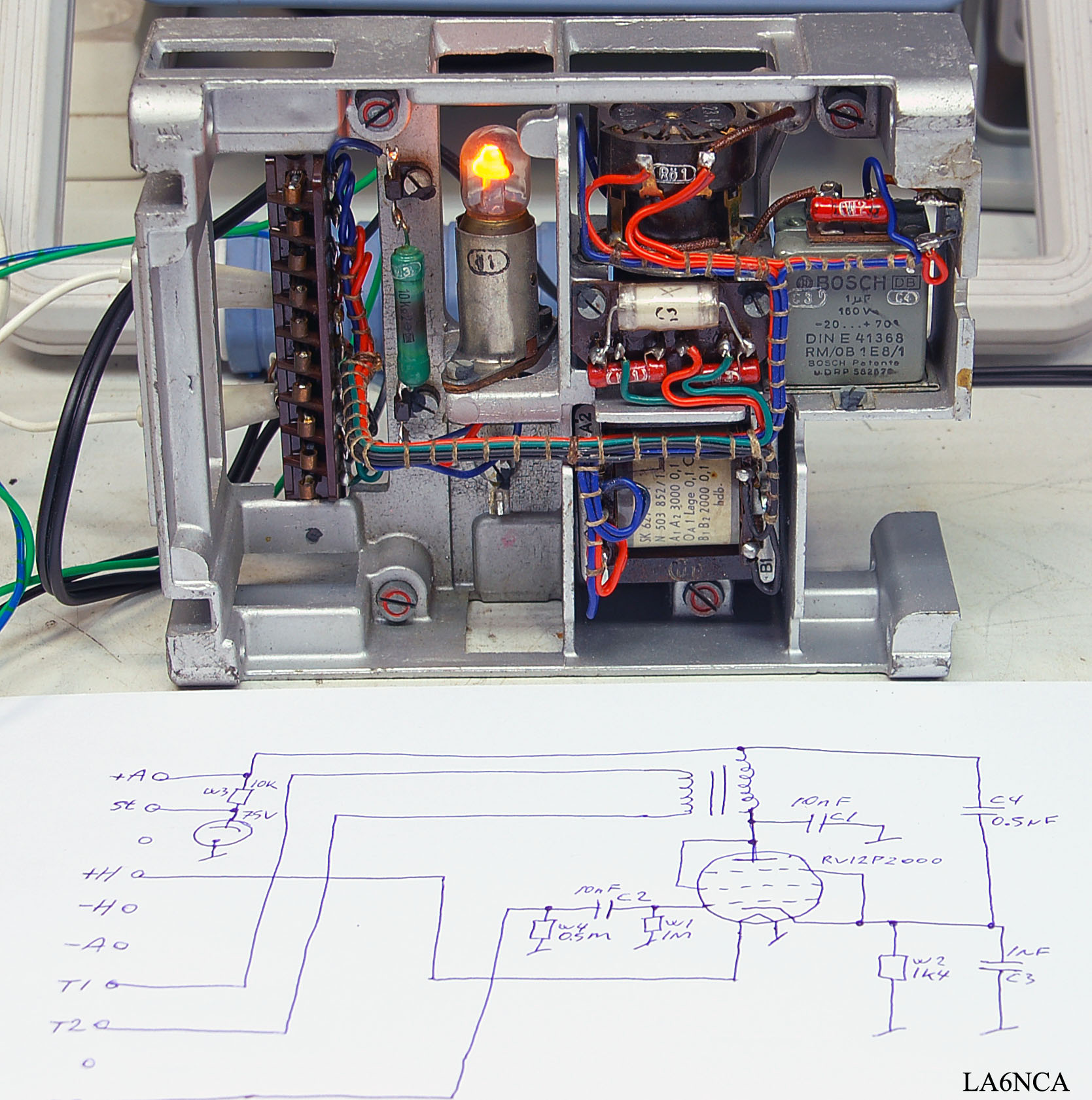
| This is the audio amplifier. It has a balanced transformer output. Output impedance is 5 kOhm Have drawn the schematic. This appears under the picture. |
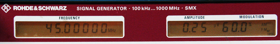
I have here connected to a signal generator with output
signal of 45 MHz, 0.25 uV with 1kHz 60% AM modulation.
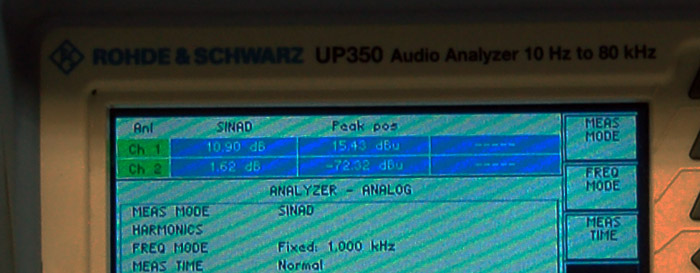
| The output is connected to a
headset and signal / noise meter. It shows 10 dB S / N ratio. This is absolutely amazing measurement results. |
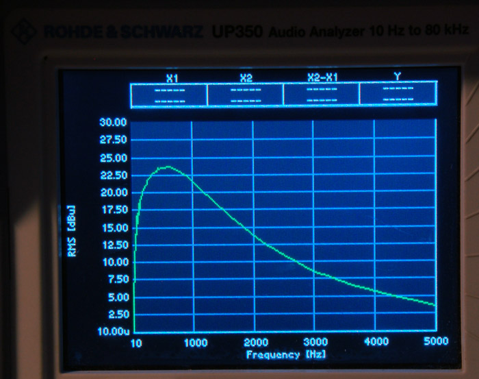
| This is the frequency
response of the receiver. Measured with a headphone connected. |
| I measure here MF filter. My own designed probe takes the signal without disrupting it. See the amazing measurement results below. |
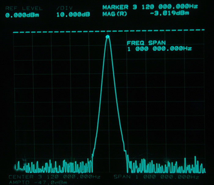
| This is MF
frequency measurement. Absolutely amazing amazing. The curve goes straight into the 100 dB noise floor. Absolutely amazing. |