 |
LA6NCA Super small spy transceiver for 80 meters. |
 |
|
LA6NCA Super small spy transceiver for 80 meters. |
|
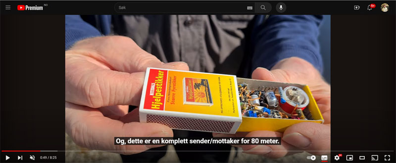
| A complete radio station hidden in 3
matchboxes. Antenna hidden in 3 fishing lines. |
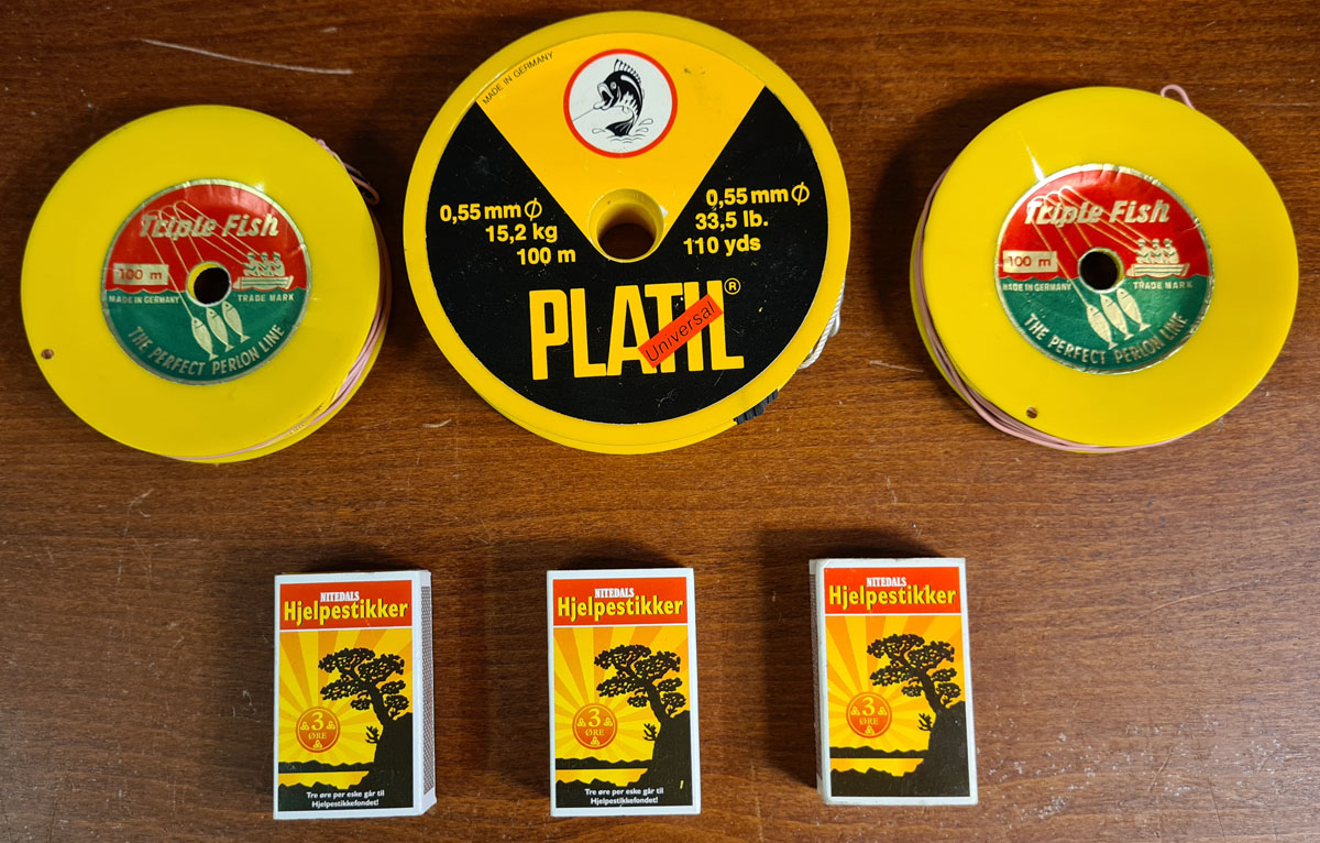
| This is the complete radio station. Antennae are the three fishing lines. The matchbox contains power, equipment box and radio station. |
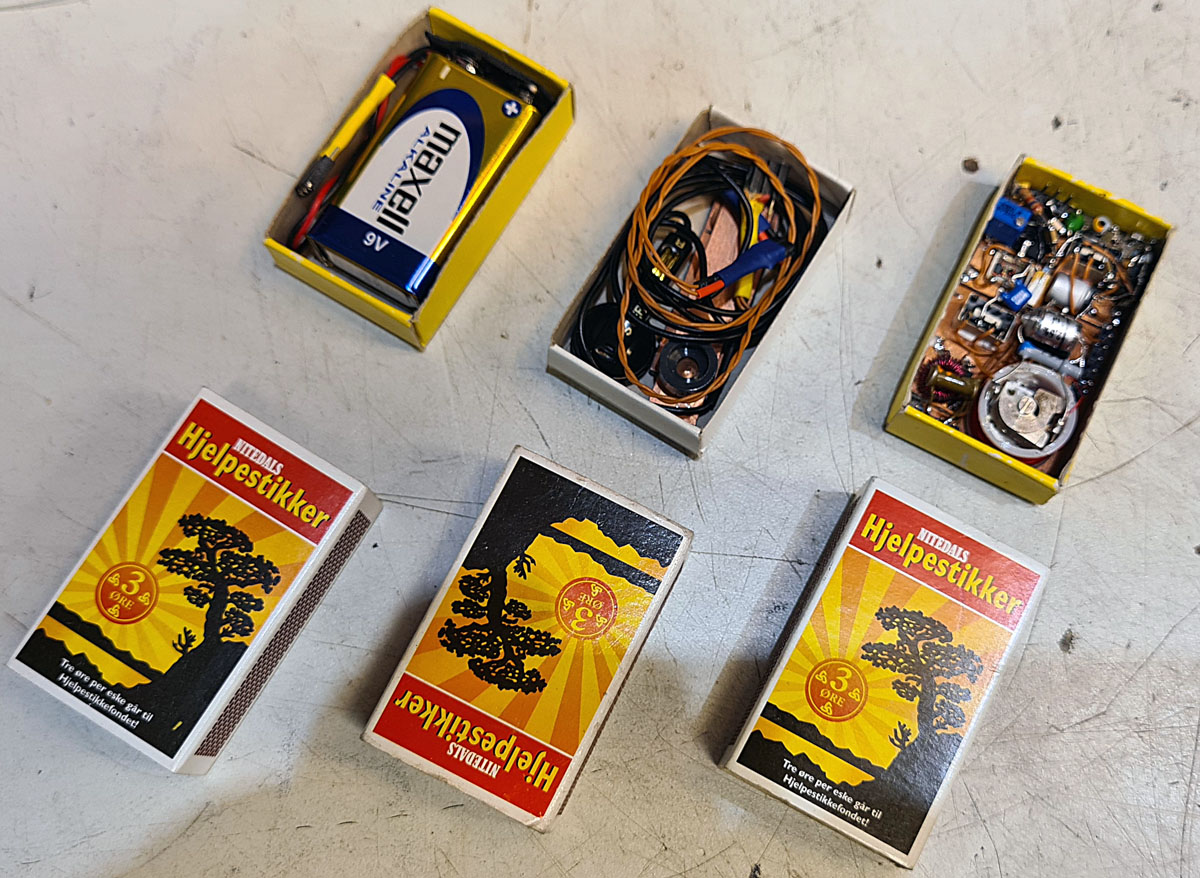
| On the left we see the power. A 9 volt
battery with power cable. In the middle we see the equipment box. It contains a headset and a morse key. On the right we see the radio station. |
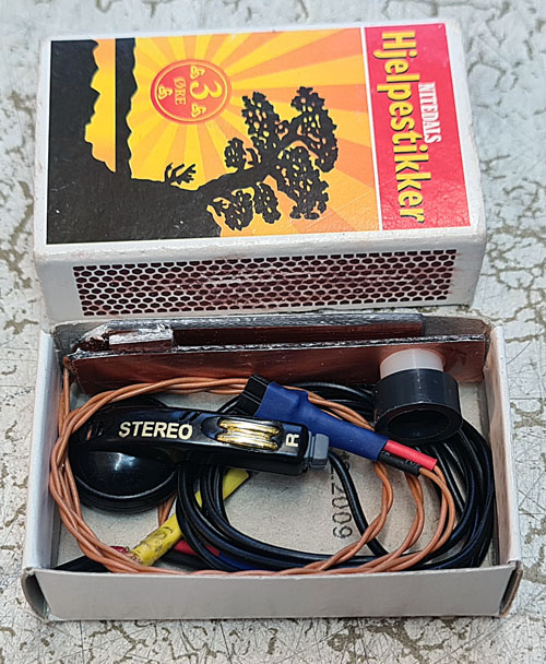
| Here you see the equipment box. It contains a super small morse key and a small earpiece. |
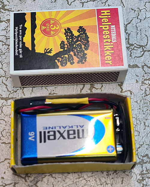
| And this is the power. The radio station is powered by a 9 volt battery. A power cable with 1/10" pins. |
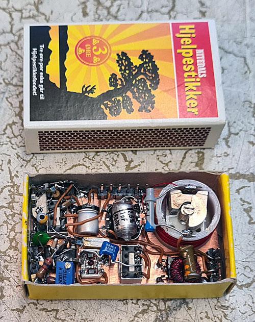
| This is a complete shortwave radio
station. It consists of an xtall oscillator at 3592 kHz, receiver and a 0.3 Watt transmitter. The modulation is CW. |
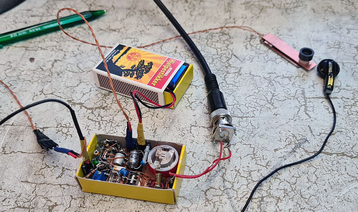
| This photo was taken during my first QSO. 120 km to a station in Oslo. Here we see the Morse key, the earphone and the power. The wire on the left is for the earphone, but also has a connection to an audio recorder for my youtube video. |
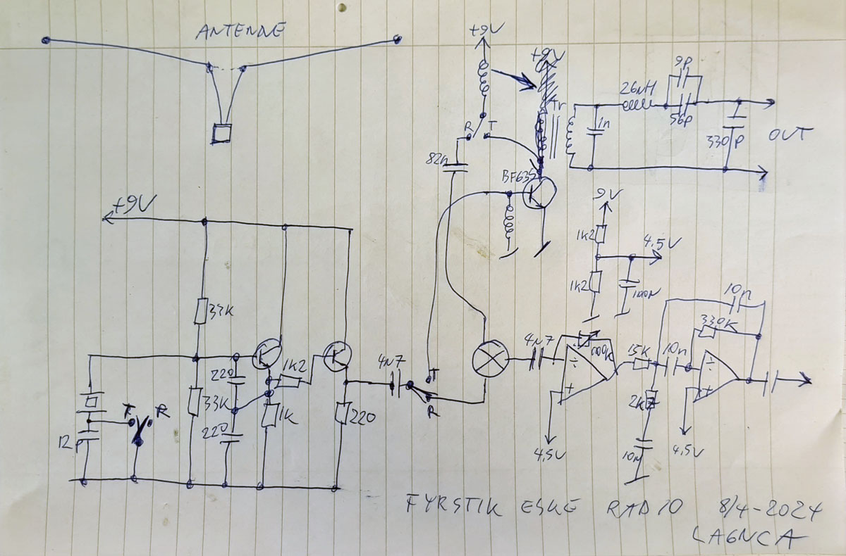
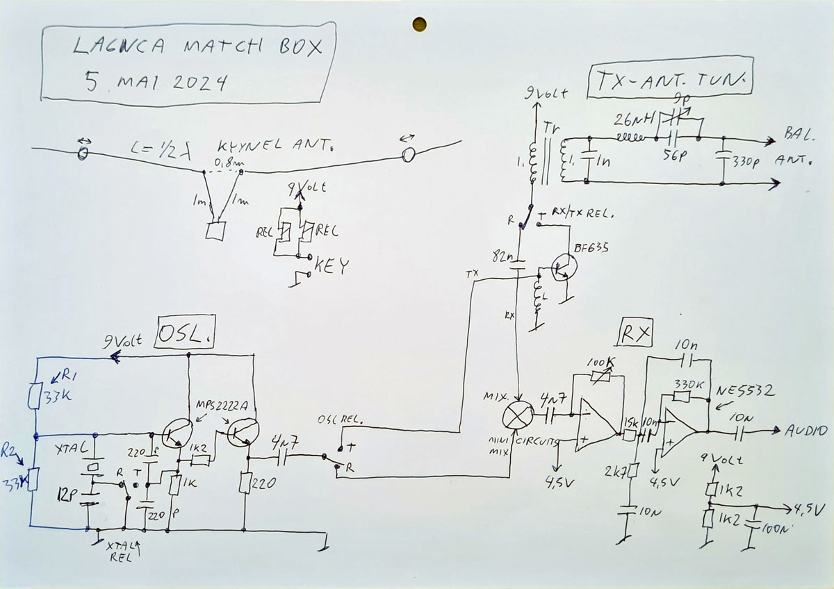
| This is the electrical schematic I used during the
design and construction process. The oscillator is on the left. The receiver is at the bottom right. The transmitter and antenna tuner are at the top right. |
!!! This is the drawing
from the video. There I had forgotten R1 and R2 in the
oscillator. !!!
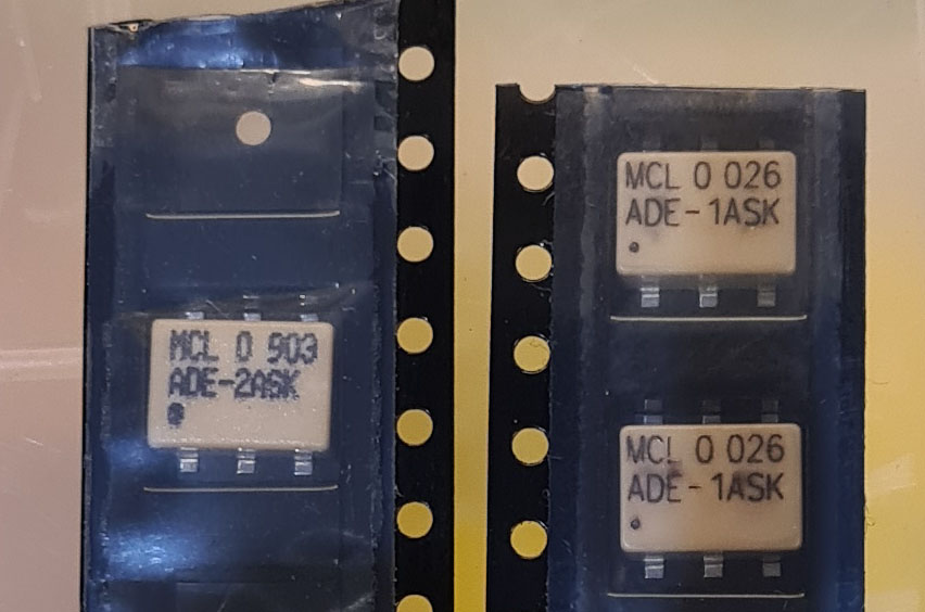
Mixer is mini circuits ade-1ask or ade-2ask.
Other mixers that go down in this frequency range work fine.
RECEIVER
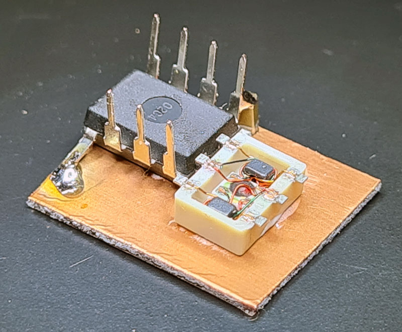
| Here I have started the construction of the receiver.
It is placed on a small 1mm circuit board. The main parts are an NE5532 opamp and a mixer ADE-2ASK. |
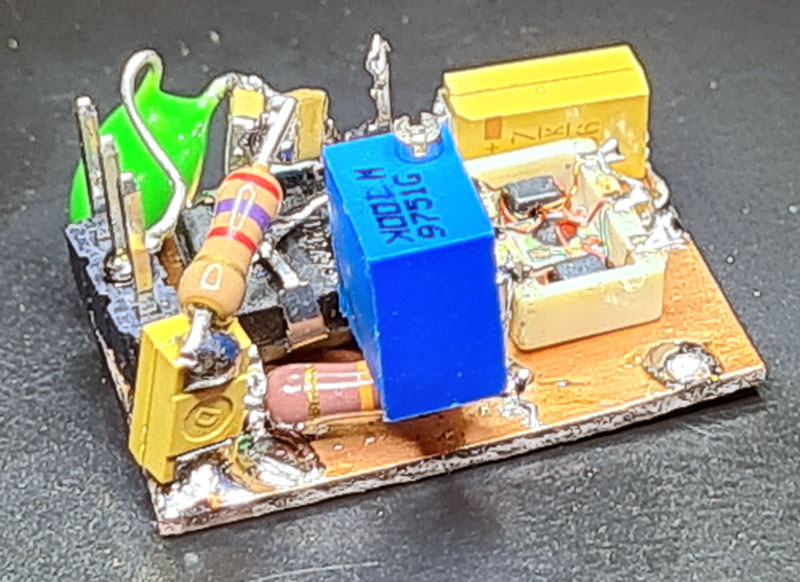
| Here we see the finished receiver. On the left are three pins. This is the headset output. The blue component is the volume control. |
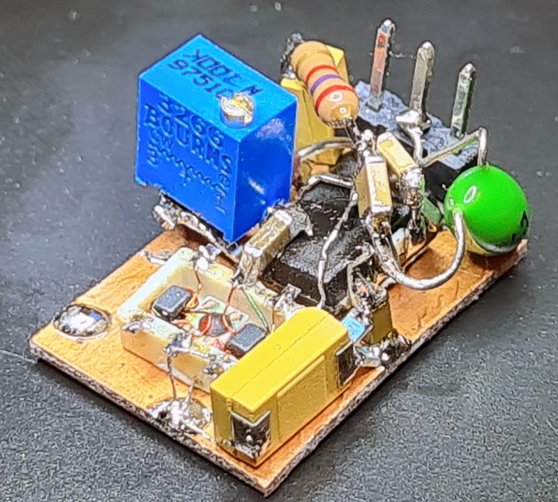
| To reduce the size, I have used a mixture of normal components and SMD components. |
OSCILLATOR
| The oscillator also consists of both regular components and SMD components. |
TRANSMITTER
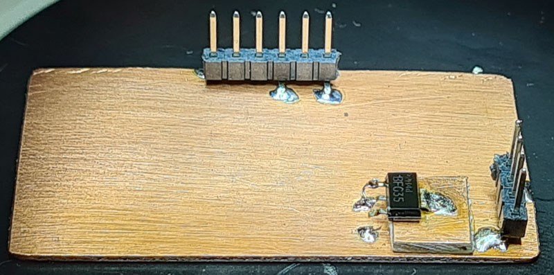
| This is a 1mm PCB that fits in a matchbox. On this plate I will mount the receiver and the oscillator. Directly on the board, I will mount the transmitter and antenna tuner. Pins on the right are the antenna output. Pins on the long side are power input and key input. |
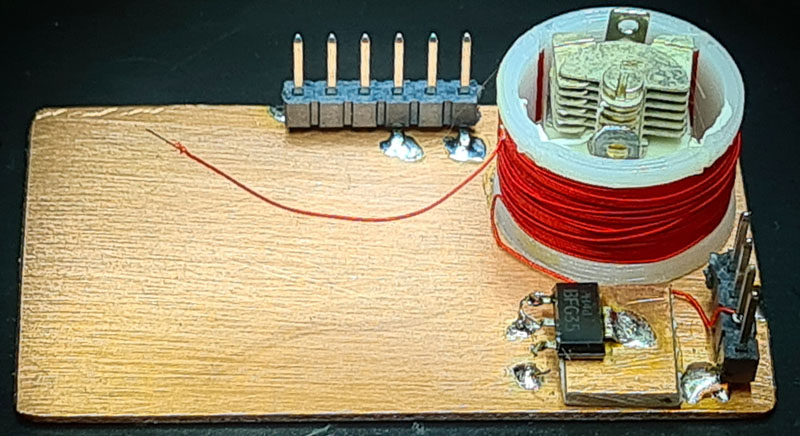
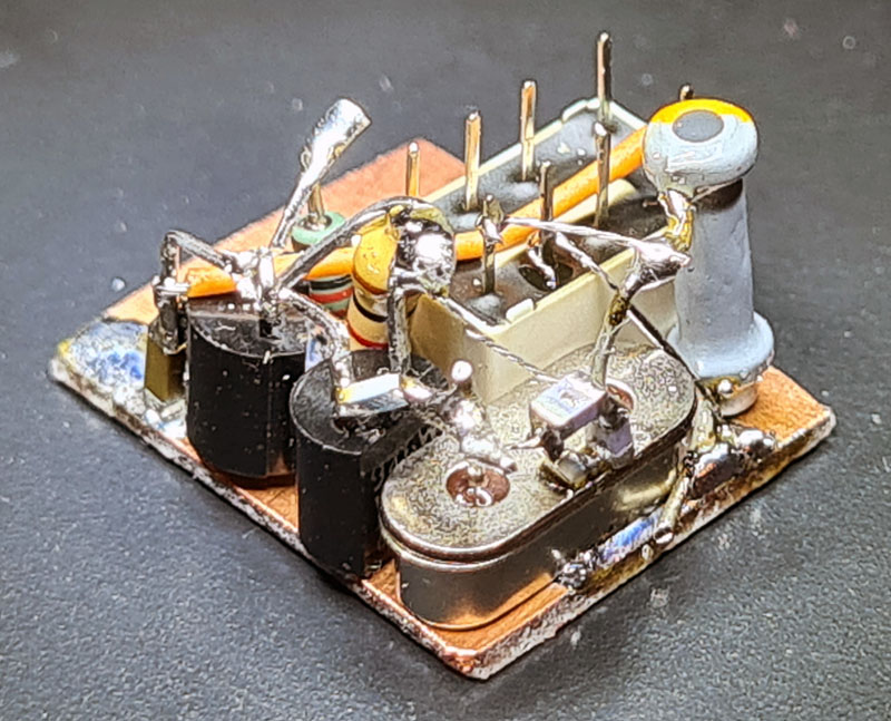
| Here I have started with the installation of the transmitter transistor and the antenna tuner. |
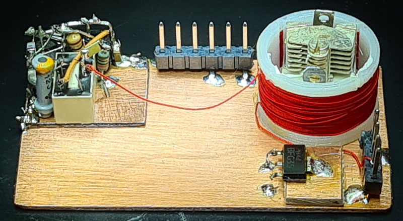
The oscillator is also mounted here.
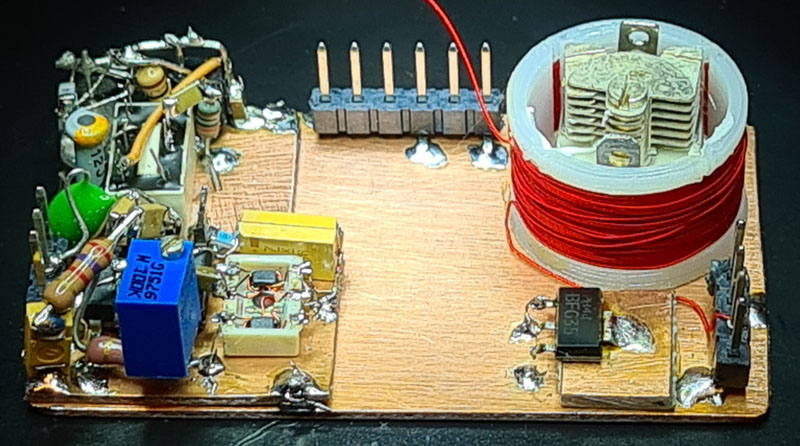
Here the receiver is mounted.
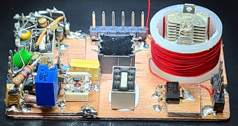
And here the Rx/Tx relay and the transmitter's transformer are
mounted.
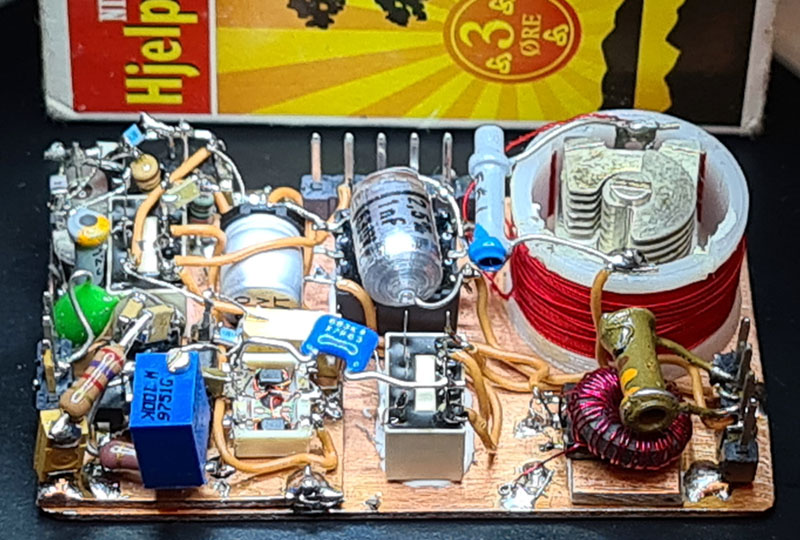
| Now the whole radio is finished. It consists of a receiver with uV sensitivity and a transmitter of 0.3 Watt. |
KYYNEL ANTENNA
| This is the antenna that was used on the Finnish
radio KYYNEL in the Finnish Winter War. It is a fantastically efficient NVIS antenna. It is easy to set up out in the field. The antenna is balanced and connects directly to the radio. Therefore, the radio also has a balanced antenna connection. |
VIDEO YOUTUBE
https://youtu.be/e1t1x3v-trU