 |
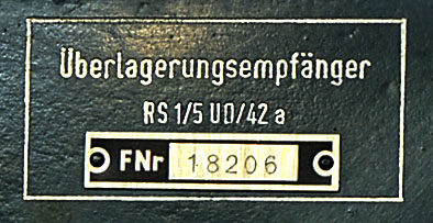
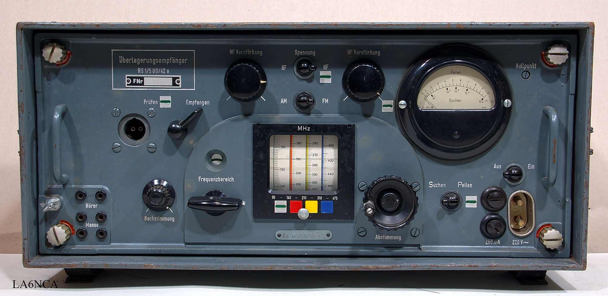
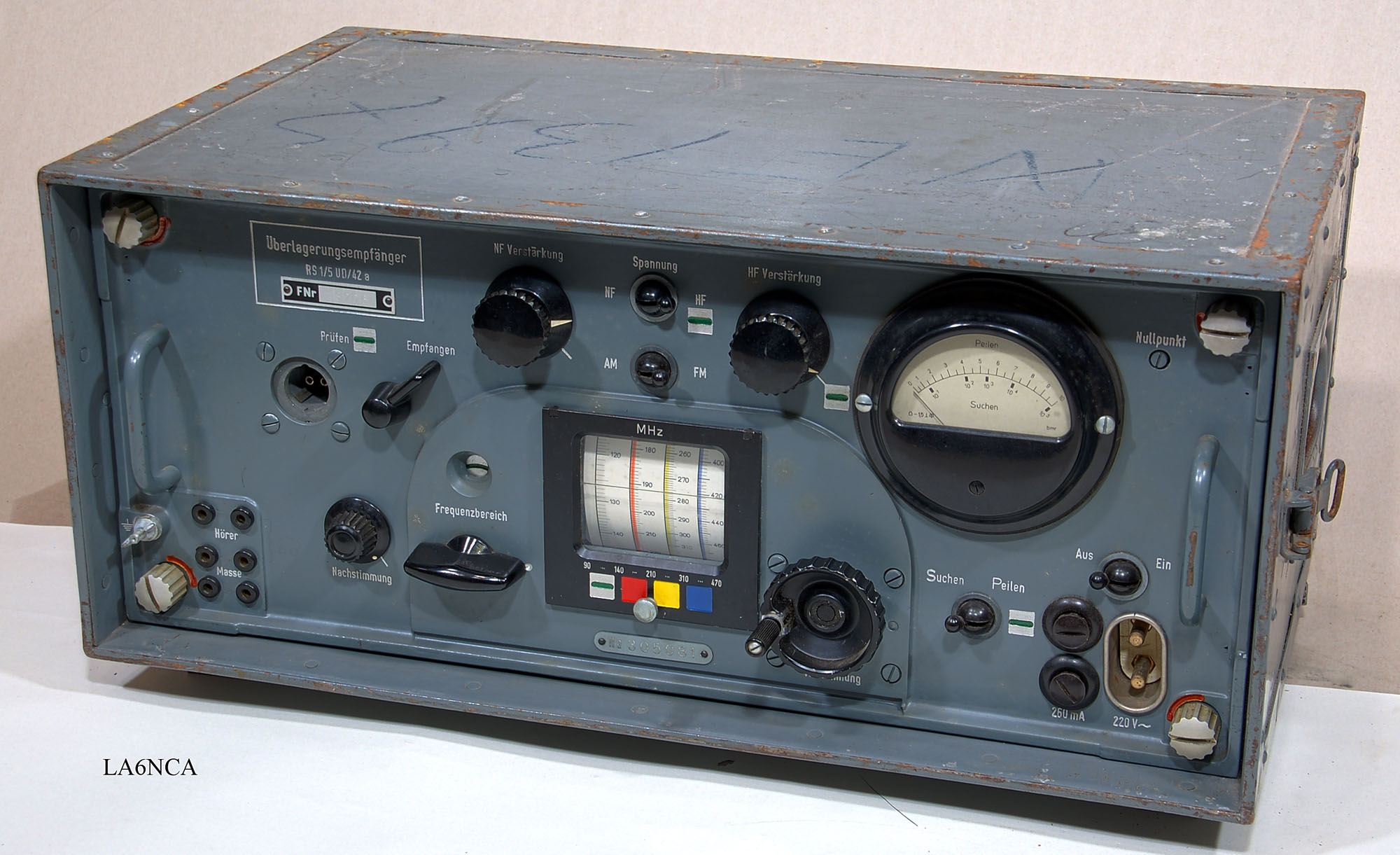
LA6NCA WW2 RADIO PAGE Fu MB 4 (Samos) Typenbezeichnung: RS 1/5 UD/42a |
 |
|
LA6NCA WW2 RADIO PAGE Fu MB 4 (Samos) Typenbezeichnung: RS 1/5 UD/42a |
|
| I will on this page show the
special design of the Rohde & Schwarz receiver SAMOS. Lorenz, Telefunken and R&S has completely different design methods. I am very impressed with how good EMC design of this receiver is. Shielding and filtering of power and radio signals are absolutely stunning. Consider that it is 72 years since it was manufactured. |
 |
 |
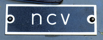
ncv
is the secret code for Rohde & Schwarz
50a.jpg
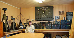
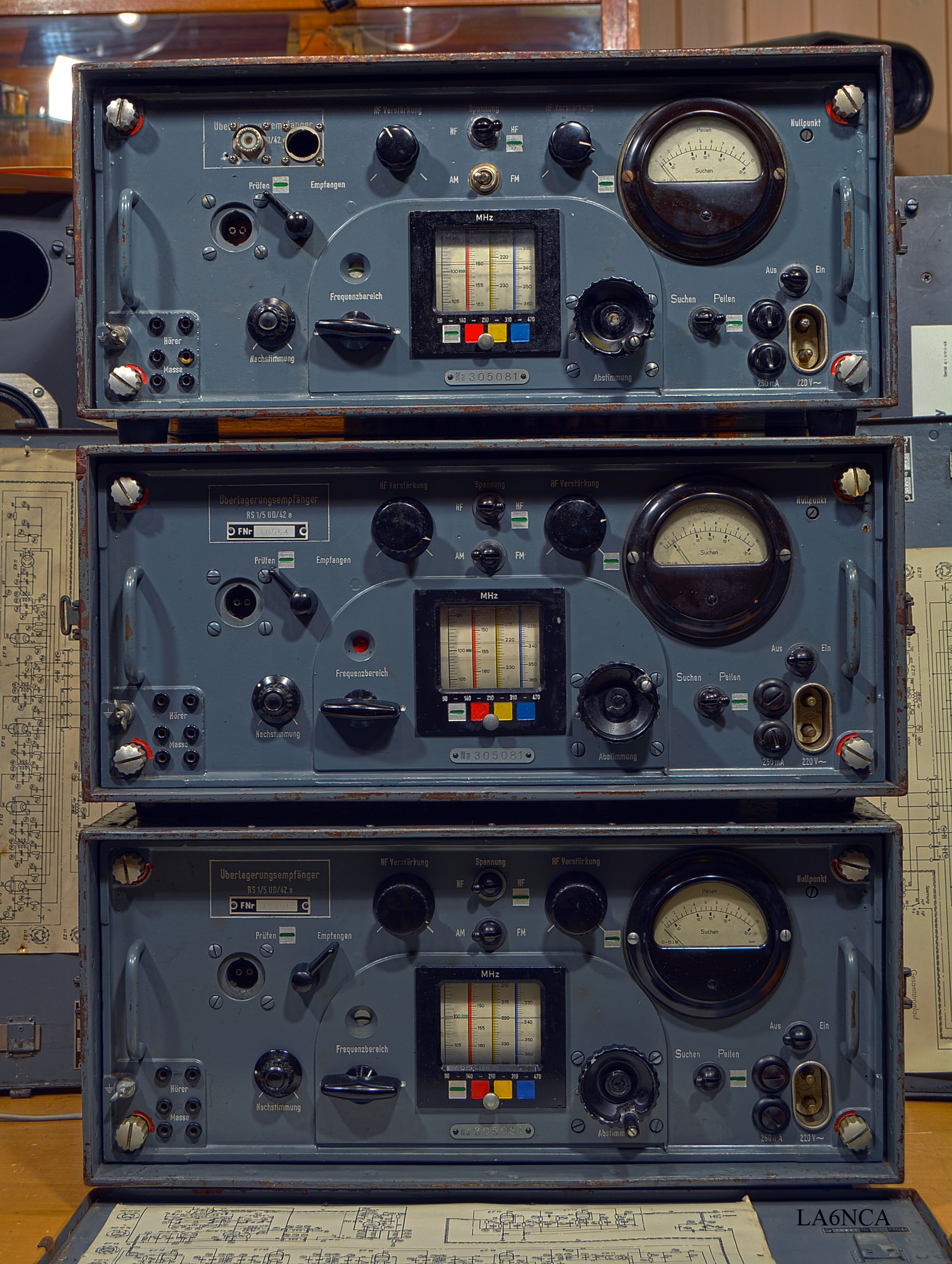
Here are my three SAMOS.
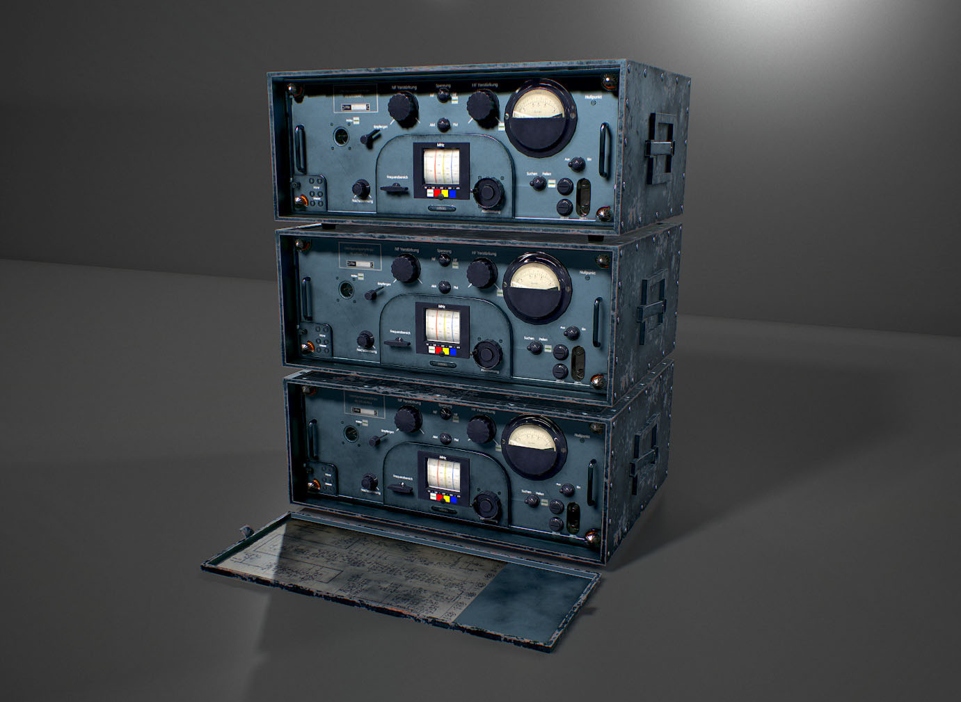
Dalton Sowah 3Dartist has made this nice picture of my Samos.
LINK
LINK2
12a.jpg
| German army used the Samos
receiver to search for enemy radar activity. By attaching a direction finder antenna, the receiver can also be used to find the source of enemy radar signals. Samos was also used for calibration of German radar transmitters. |
| Frequency range: 90 –
470 MHz Input impedance: 150 ohm balanced IF frequency: 2.5 MHz IF bandwidth: 50 kHz Selectivity: 12 uV for 1 V output. Modulation: AM and FM Instrument output: RF level or LF level. Power input: 220 VAC, 34 Watt Dimension: 515 x 245 x 300 mm Weight: 20 kg |
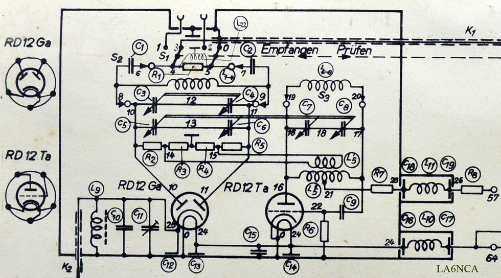
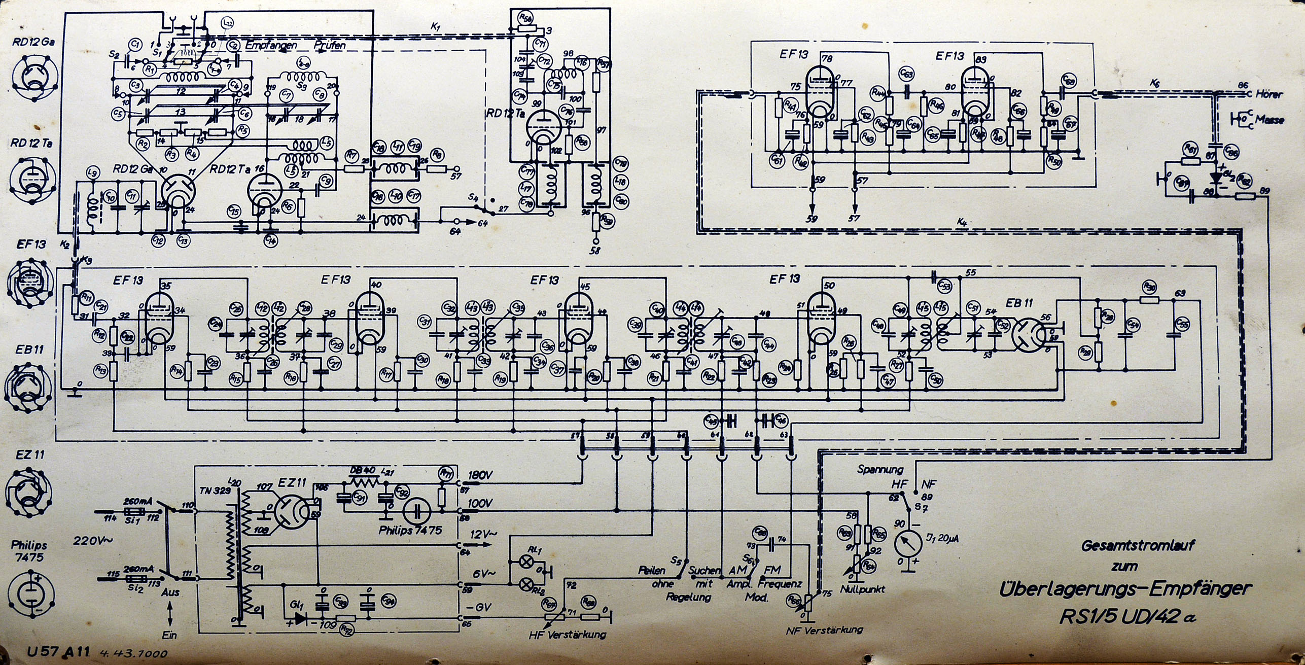
| Here is the circuit diagram. It is mounted on the back of the front lid. The results of my test is stunningly good. Frequency accuracy is exactly all the way up to 470 MHz. |
46a.jpg
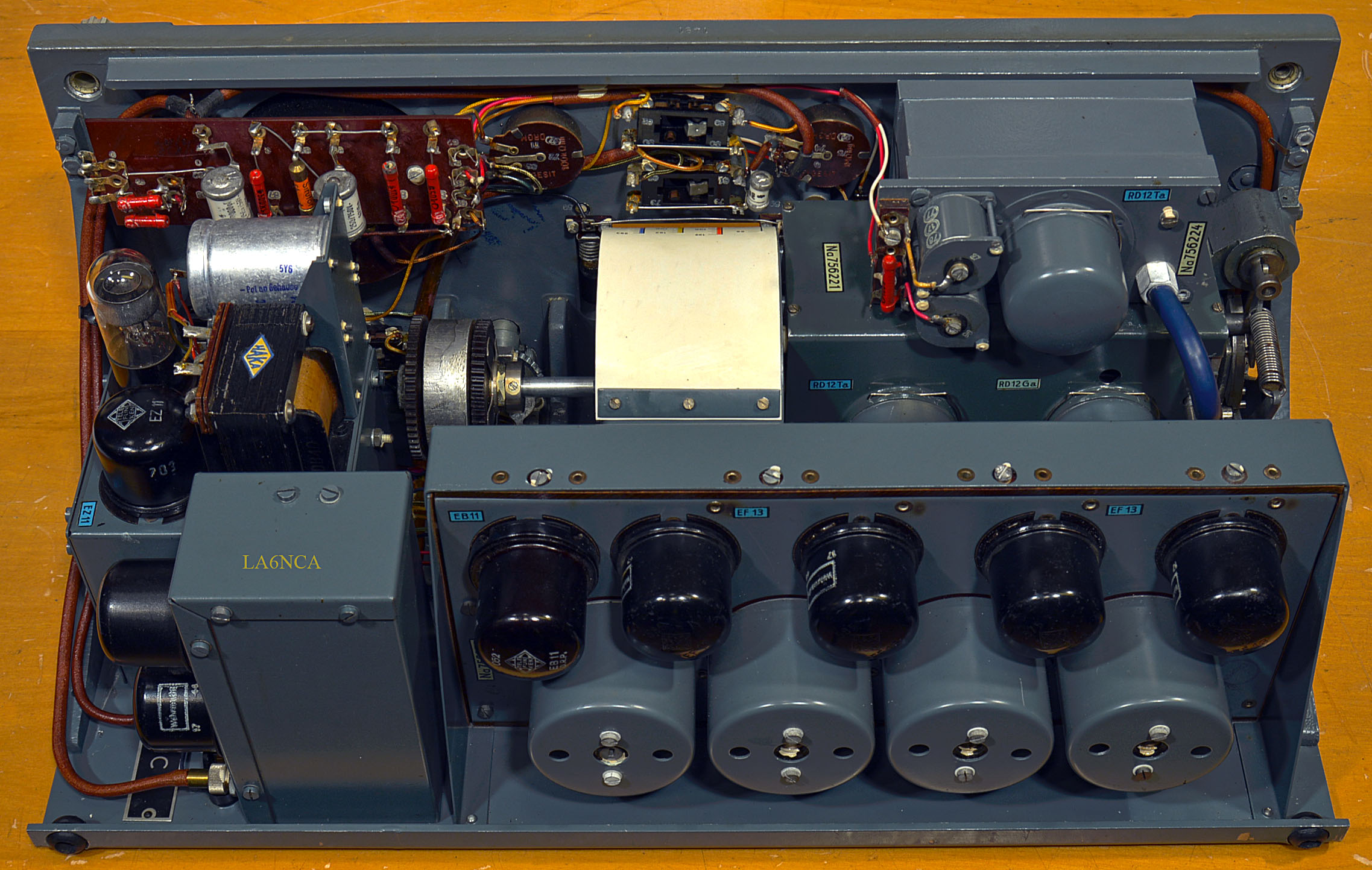
The inside of SAMOS.
48a.jpg
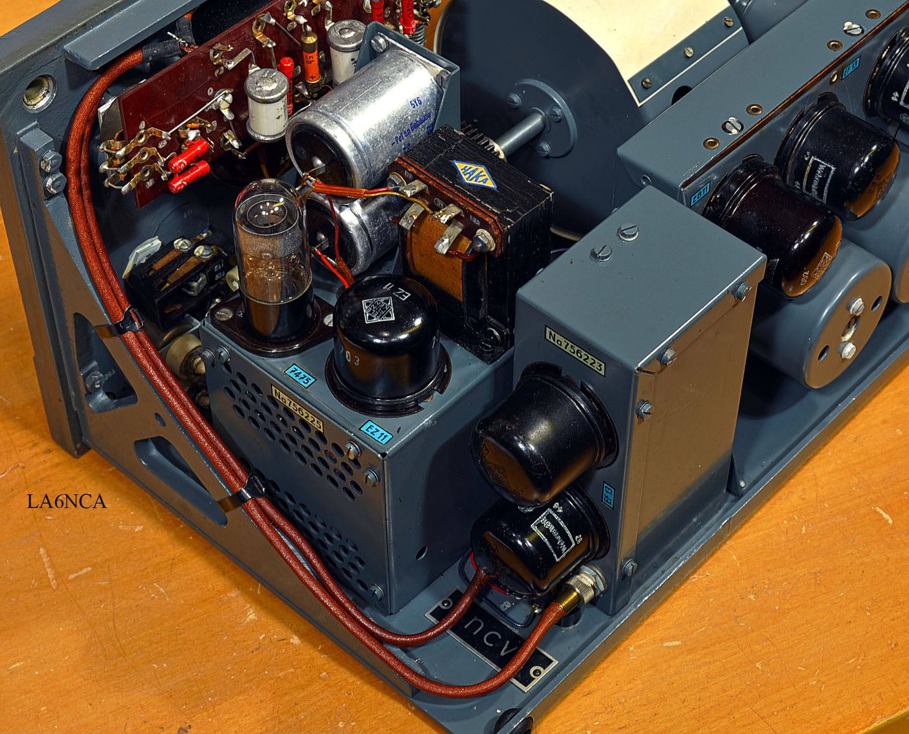
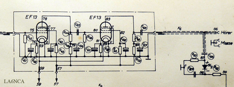
Here is Power Supply and
audio amplifier.
We also see company sign "ncv"
49a.jpg
And here we see the RF
section and calibration oscillator.
23a.jpg
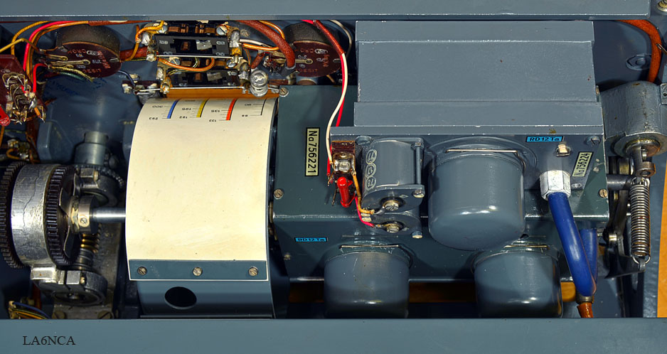
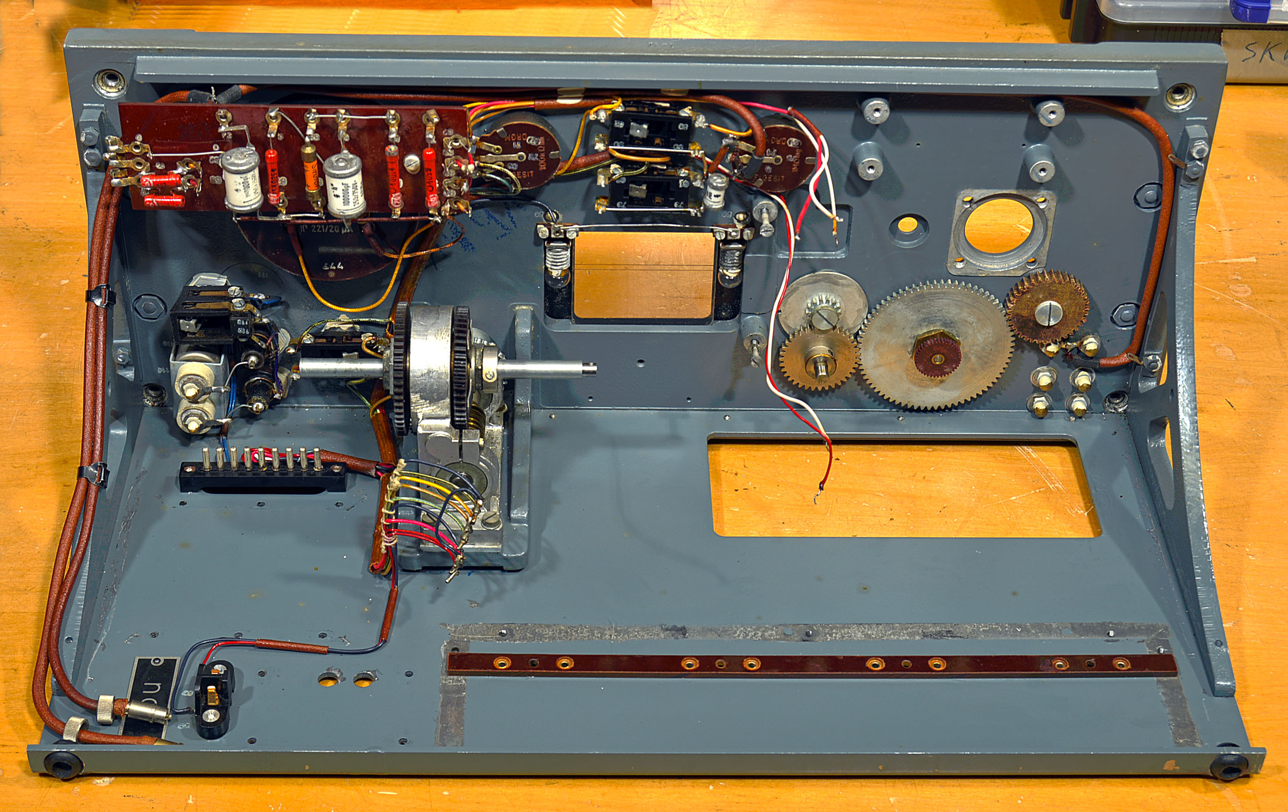
| Here is the frame that the
different parts are mounted. Fantastic neat design. We can see the connectors for Power and audio amplifier to the left. The gears on the right is for the band switch. The shaft for the frequency setting can be pushed onto the RF section. |
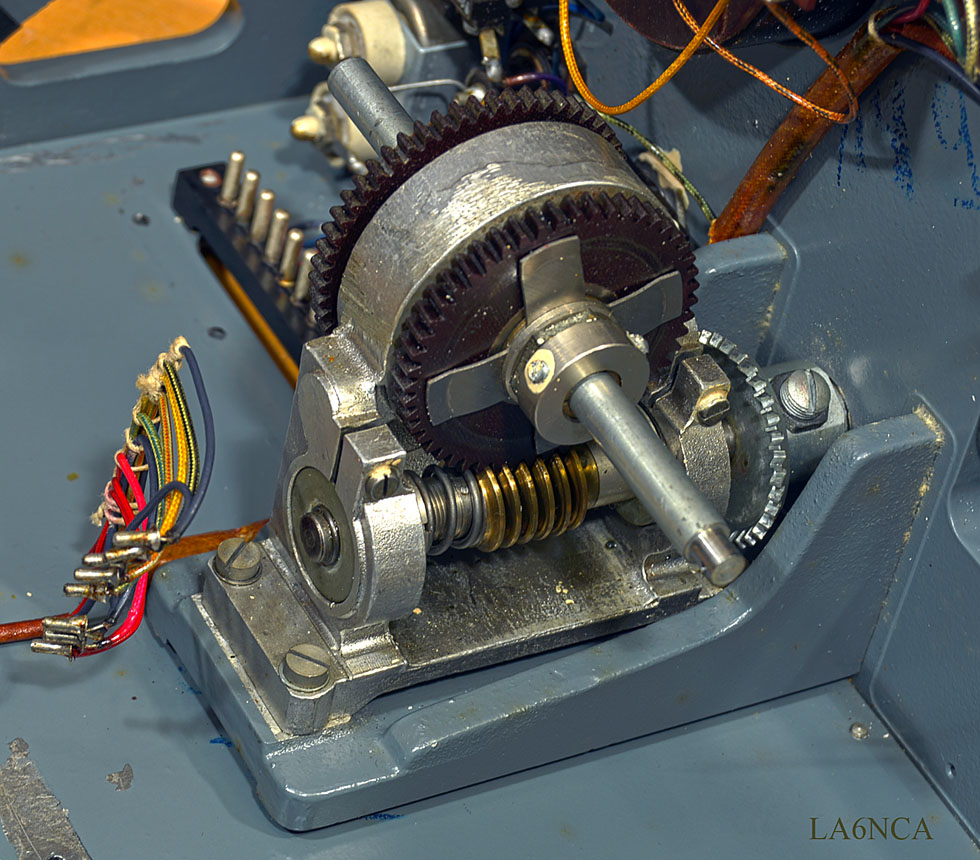
A wonderful fine worm gear for frequency settings.
RF
SECTION
Here's RF section with local oscillator and mixer.
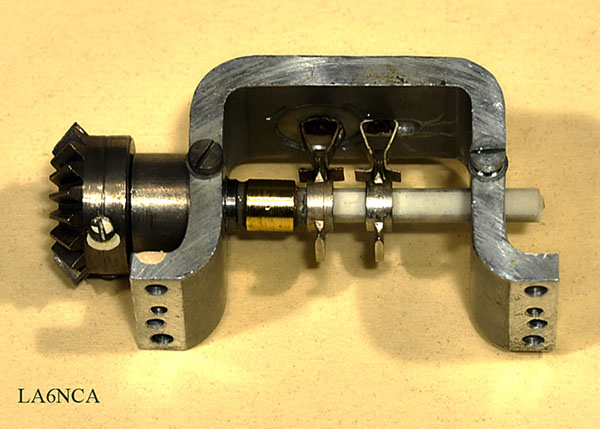
| This is the connection to
the frequency setting shaft. The shaft can be moved in all directions. We can see also the filters for glow voltage and anode voltage. |
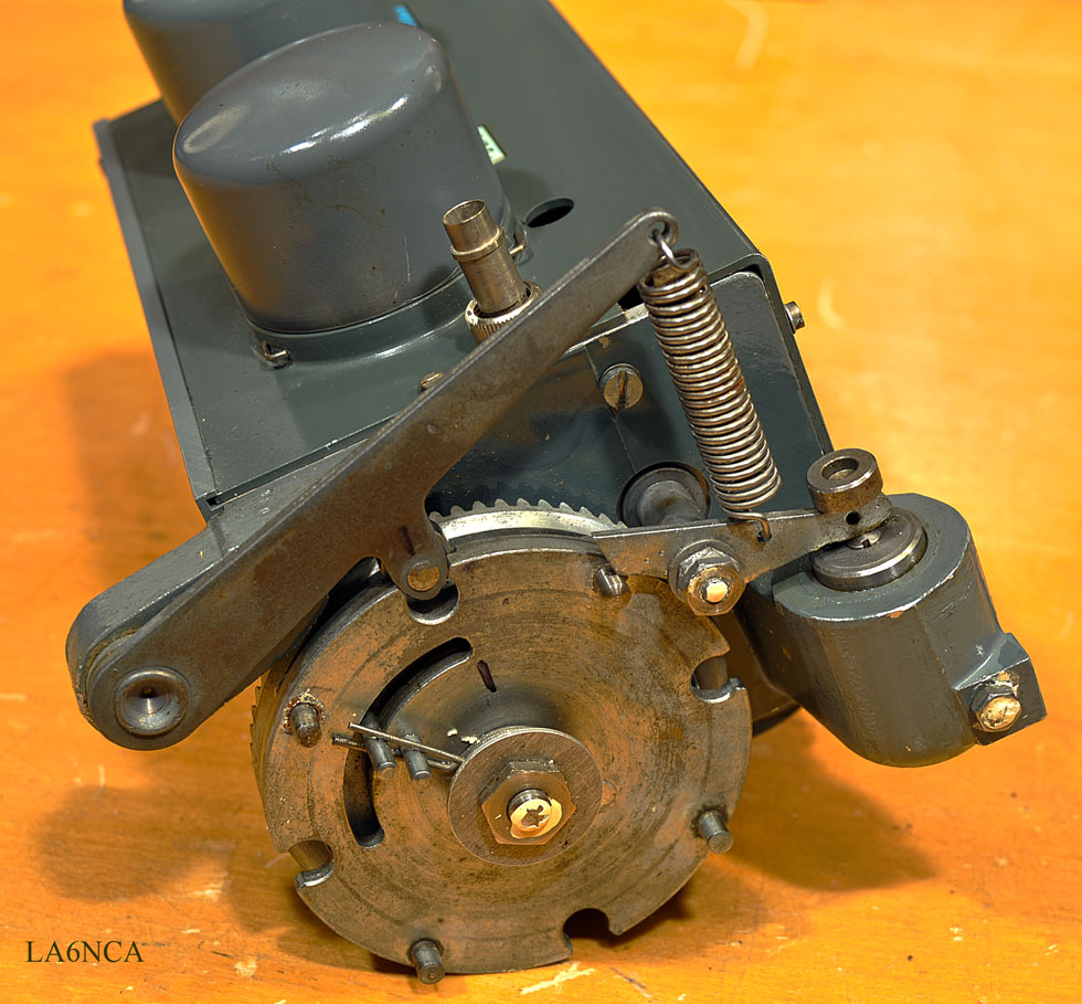
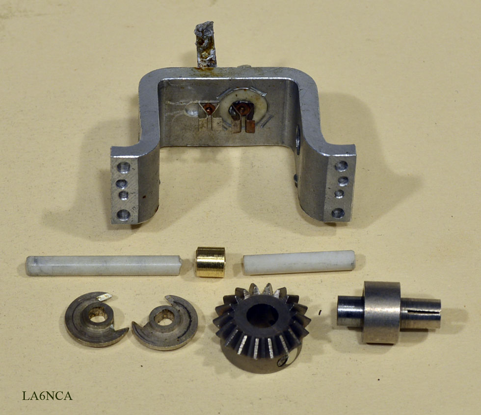
| Here we can see the
mechanics for the band switch. A wonderful fine pneumatic cylinder is connected to the mechanics. Its function is to dampen the motion of the frequency selector. |
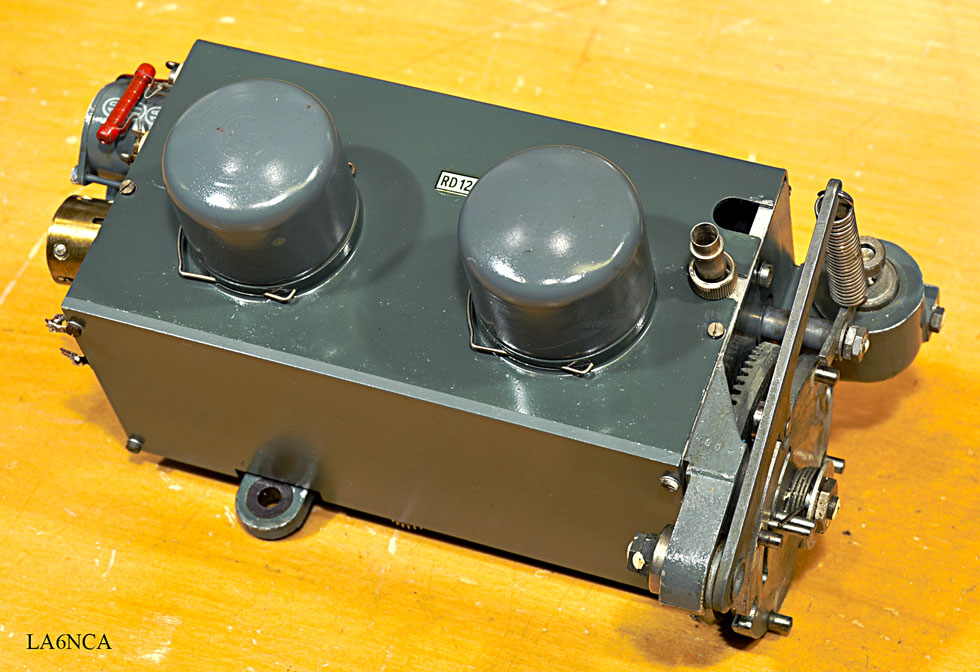
| Here are the local
oscillator and RF mixer. MF frequency is 2.5 MHz at connector K2. Connector K1 is 100 MHz calibration oscillator input. |
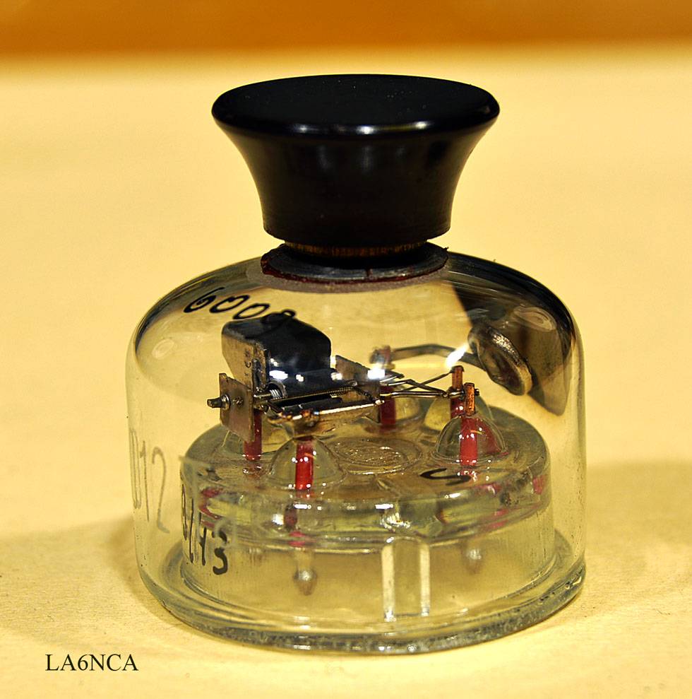
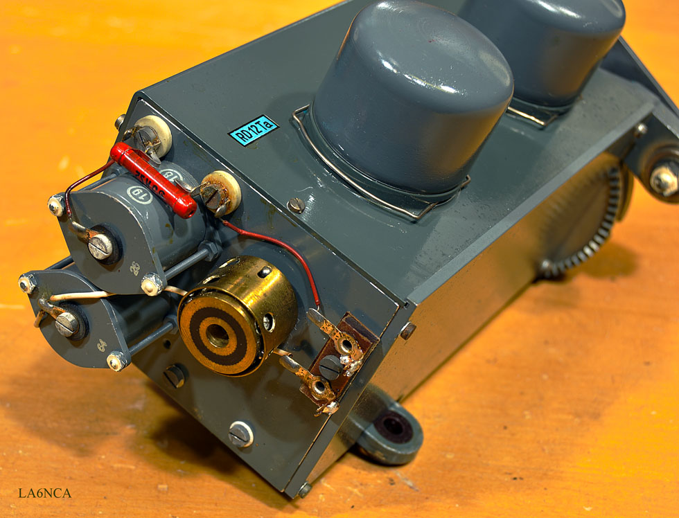
| Closeup of tube triode
RD12Ta used in local oscillator and the frequency
calibrator. This triode is designed for extremely high frequencies. See the short distances from the contacts to the triode. |
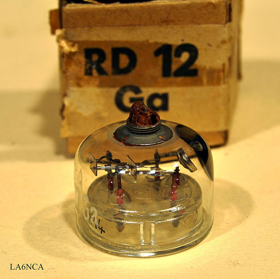
| Detector diode RD12Ga. Here also all distances so. It therefore function for very high frequencies. |
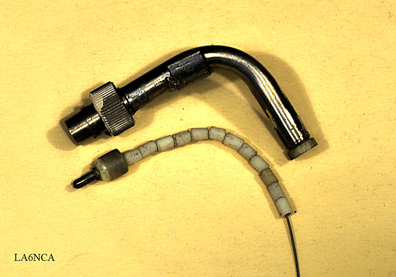
| These are coaxial cables
from the RF seksionen. It was destroyed when I dismounted radio. I must therefore mount it again. The insulation on the cable are small porcelain pieces that are threaded onto the inner conductor. |
| This is the switch that
selects between calibration oscillator and the antenna. Porcelain shaft was broken. I machined a brass sleeve to splice the porcelain shaft.. |
I have now repaired the broken porcelain shaft.

36a.jpg
| Here's antenna switsjen
mounted. Antenna input is connected directly into the antenna switch. In this way we achieve very small distances for the high frequencies. Look at the fantastic mechanics of the oscillator and mixer. |
RD12Ga Double Diode Detector.
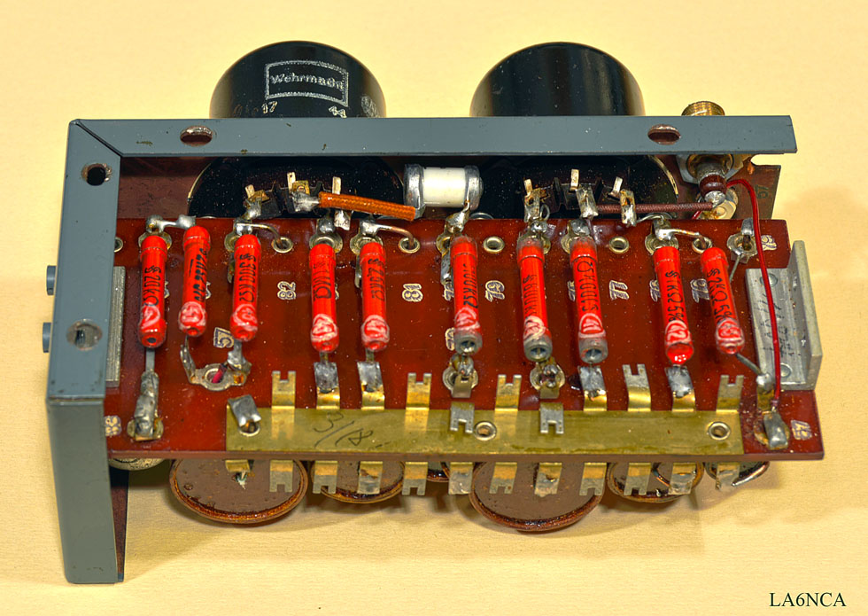
MF
AMPLIFIER AND AUDIO DEMODULATOR.
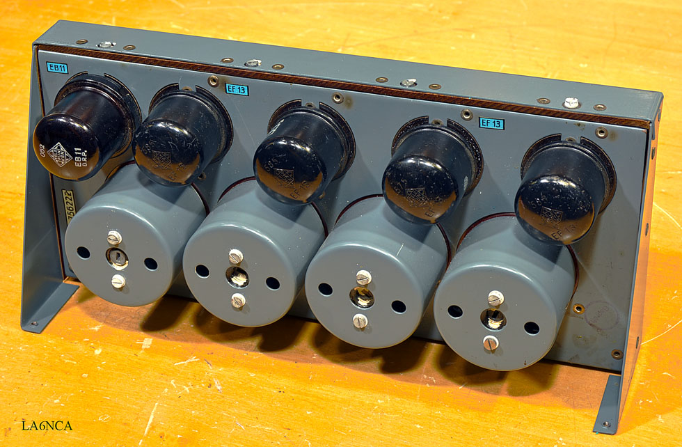
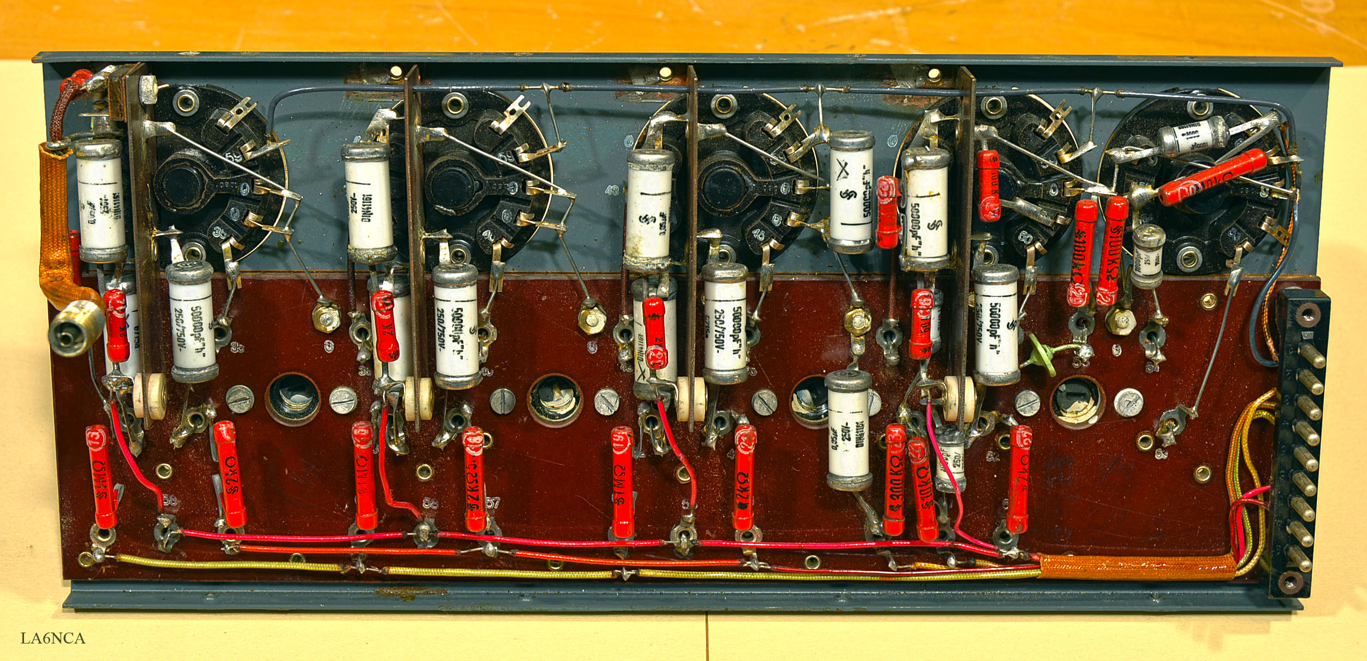
38a.jpg

42a.jpg
AUDIO
AMPLIFIER
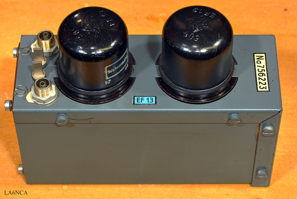
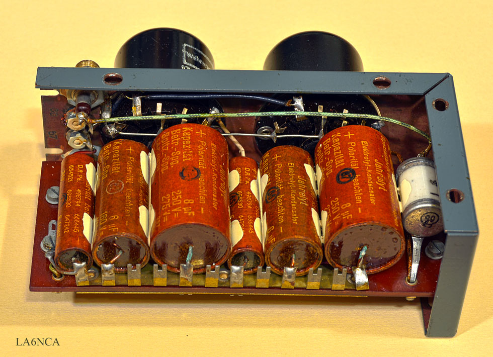
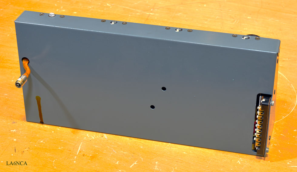
POWERSUPPLY
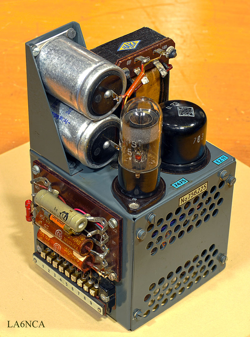
Power in this radio is amazing great design.
Very compact. The transformer is mounted inside the shielded box.
All voltages in and out of Power is connected to the connector.
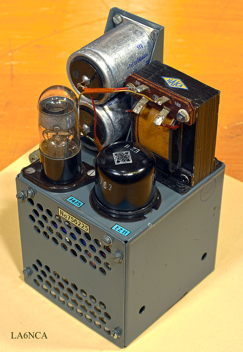
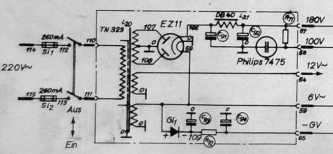
On top of Power is rectifier tube EZ11, regulator tube 7475,
capacitors and the choke.
Frequency
Calibrator - 100 MHz
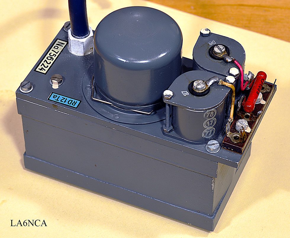
| This is an oscillator for
calibration of the receiver. See the amazing great filters for 12.6 Volt and 100 Volt. The entire oscillator is mounted in a cast aluminum box. The tube is mounted in an RF shielded lid. Fantastic design here too. |
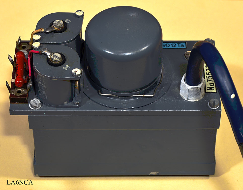
Oscillator seen from the other side.
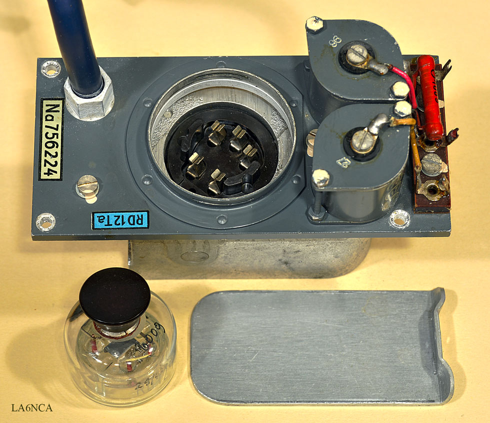
Here, the tube is removed.
Here is the special tube socket that is designed for VHF
frequencies.
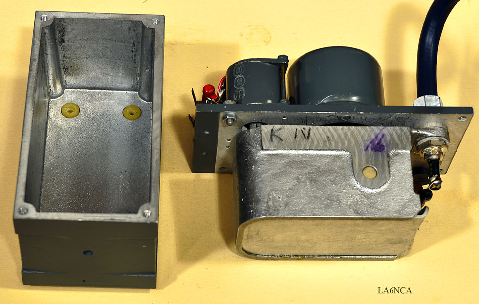
Here we see the inner shielded box.
The EMC design here is amazing good.
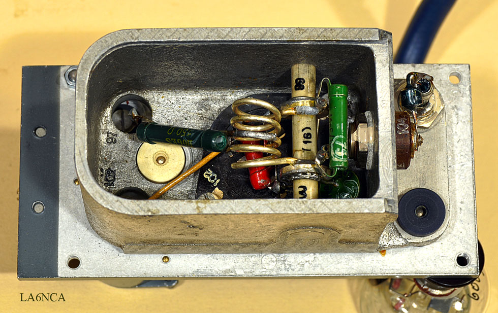
Here we see the coil and capacitor that determine the oscillator
frequency.
Look at the amazing great shield.
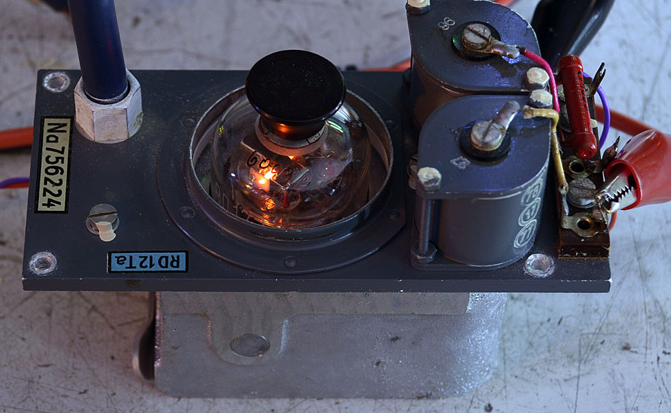
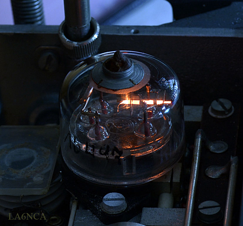
I test the oscillator.
Look at the fine tube when it glows in the dark.
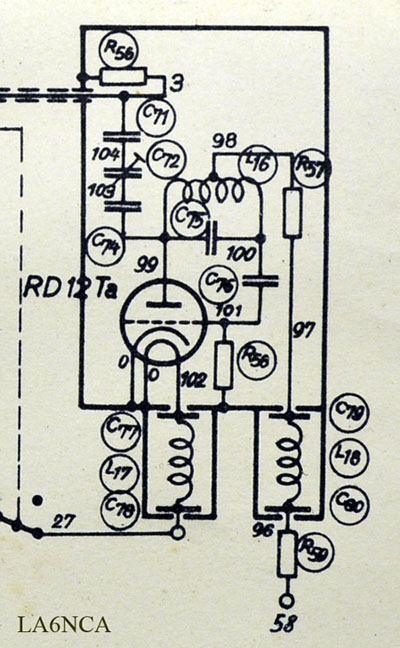
Here is diagram of the oscillator.
Voltages in is 12.6 Volt filament voltage and 100 Volt anode
voltage.
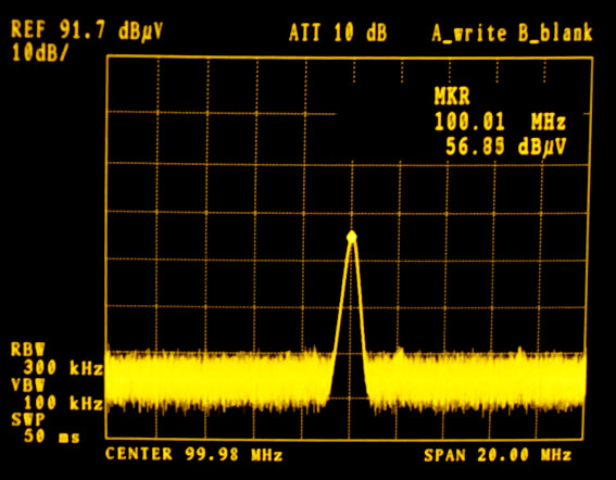
| Here we see the output
frequency. The voltage is only approximately 100uV The rate is absolutely fantastic stable at 100 MHz. After 72 years, the absolutely fantastic. I Have not calibrated anything. |