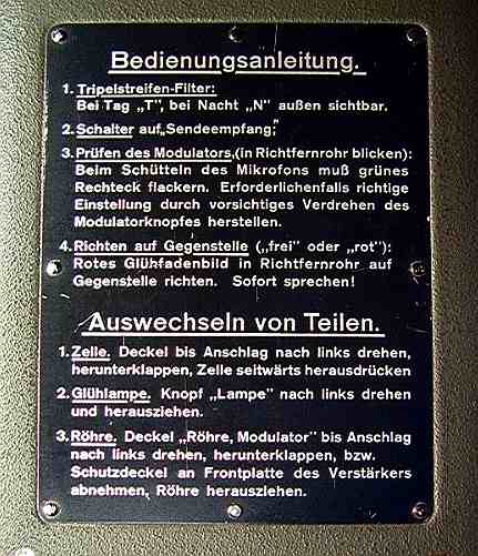
|
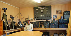
LA6NCA |
 |
|
LA6NCA |
|
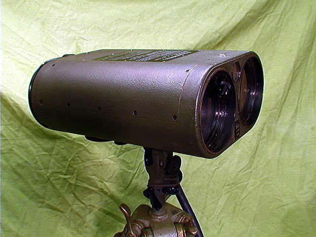
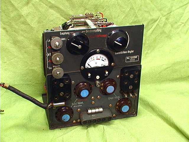
Serial no. 217675, year 1940
This is a 2-way audio communication
equipment. Red and IR filter can be inserted in the
beam. |
Technical data from the handbook:
| Optic | Receiver - 80 mm Transmitter - 80 mm |
| Tubes | Receiver, 3 - RV2P800 Transmitter, 2 - RV2P800 |
| Detector | Thalofidezelle |
| Filters | Reed, visible Reed, IR, invisible |
| Range | 4 km without filter 4 km with reed filter 2-3 km with IR filter |
| Power | 2 VDC, filament 4.8 VDC, bulb 50 VDC, detector 60 VDC, anode voltage |
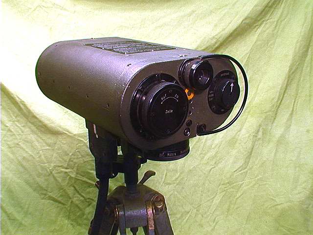
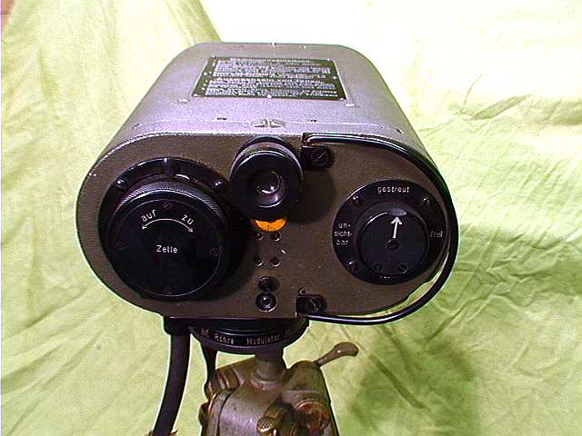
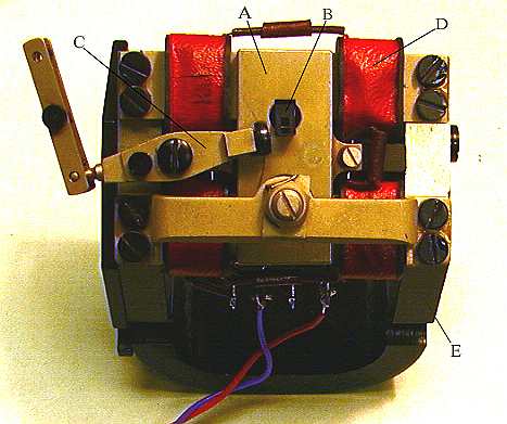
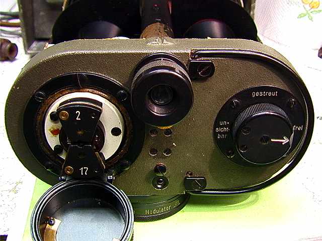
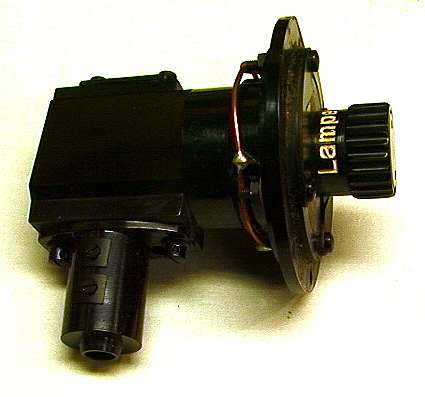
Left, light
detector.----------------------------
Mid, direction finder telescope.---------------
Right, filter selector. ---------------------------
Under, preamplifiers tube.----------------------
Tripod is also manufactured by Carl Zeis Jena. -
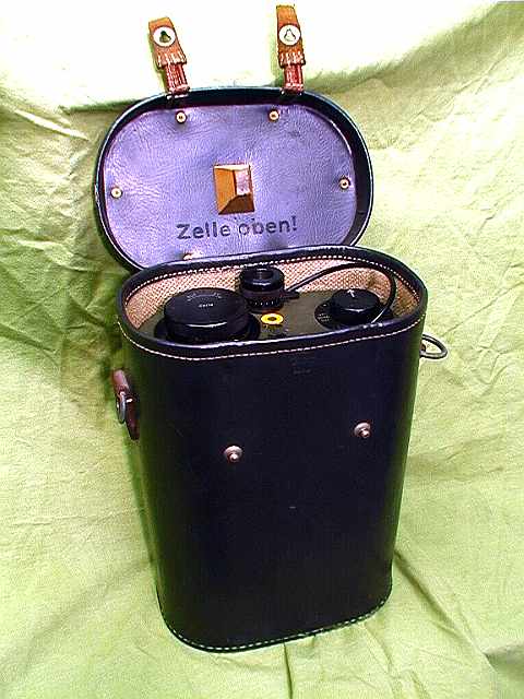
Optic unit in the case.
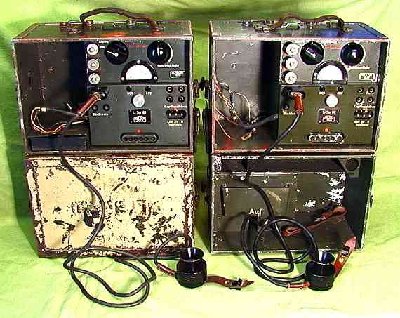
Serial no. xxxx, year 194x, ------- Serial no. xxxx, year 194x
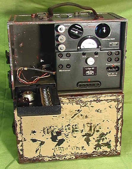
Amplifier unit with RV8P800 tubes.
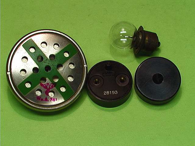
Spare parts. Carbon Microphone, light detector, bulb 4.8V- 5W
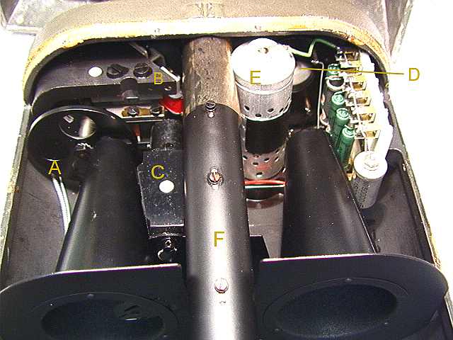
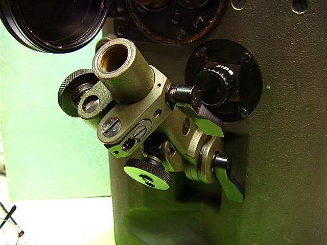
Optic unit.
A – light filters. 4 different filters can be selected with
the filter knob.
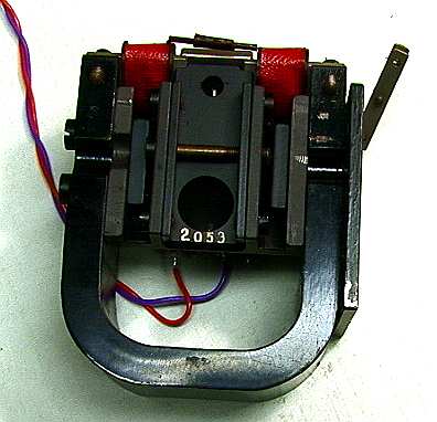
B – Light modulator with a moving
mirror.--------------------------
C – Light source with 5 Watt
bulb.---------------------------------
D - Light
detector.-------------------------------------------------
E – RV2P800, Light detector Amplifier
tube.----------------------
F – Telescope for adjustment of
direction.--------------------------
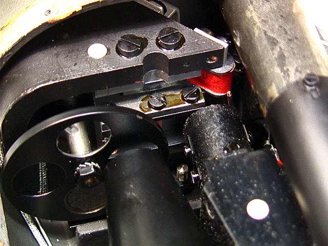
Light-modulator (11). Filters (IR and red).
Her we have the light phase prism mounted on the moving iron.
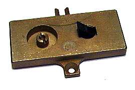
Left - Here is the light detector behind the
cover.
Right – Here is the filter selector.-----------------
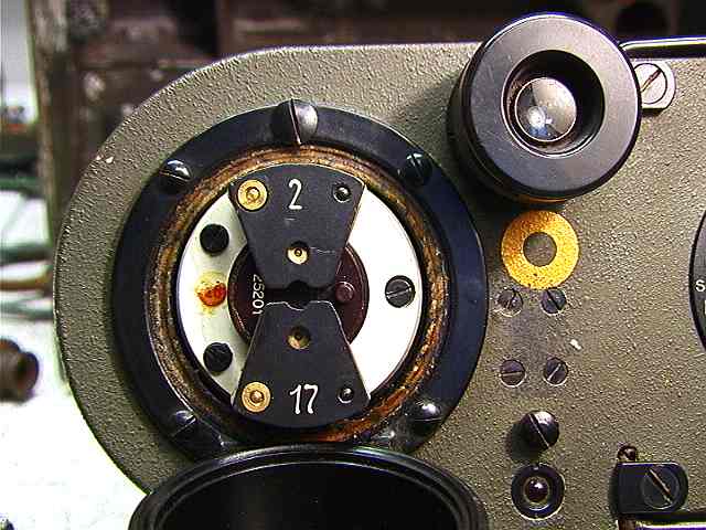
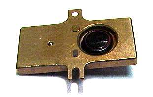
Light Detector. Look at component 26 in the
schematic (node 2 and 17)
Detector is mounted on a porcelain structure. This gives a very
stabile fastening of the detector.
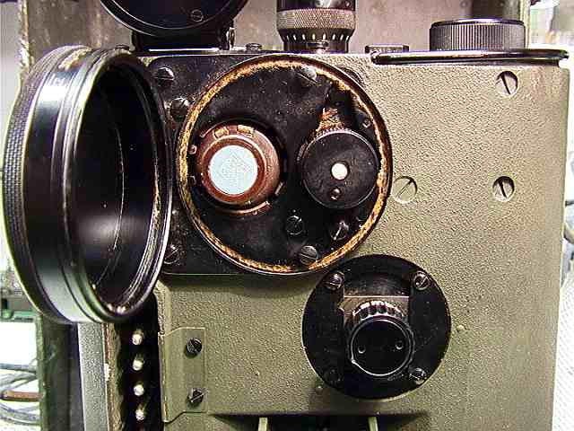
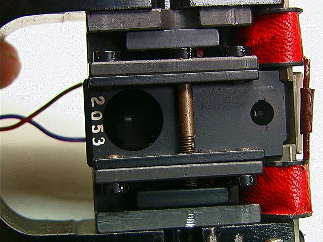
Light Detector amplifier tube and light bulb.
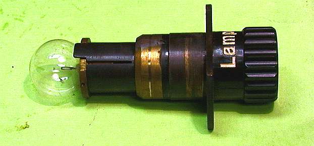
Light bulb 4.8 V, 5 W.
Stativfestet. Skruer for sideretting og
høyderetting av optikken.
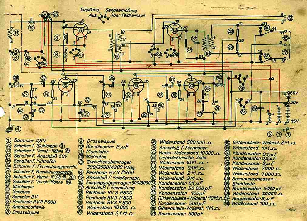
Here is the schematic located inside the amplifier unit.
Components left of the dotted line is located inside the optic
unit.