 |
LA6NCA RADIO PAGE Torn. Fu. d 2 Portable VHF tranceiver Tornister - Funkgerät |
 |
|
LA6NCA RADIO PAGE Torn. Fu. d 2 Portable VHF tranceiver Tornister - Funkgerät |
|
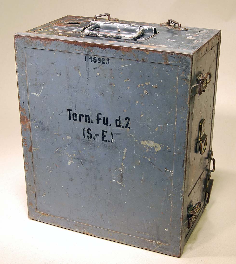
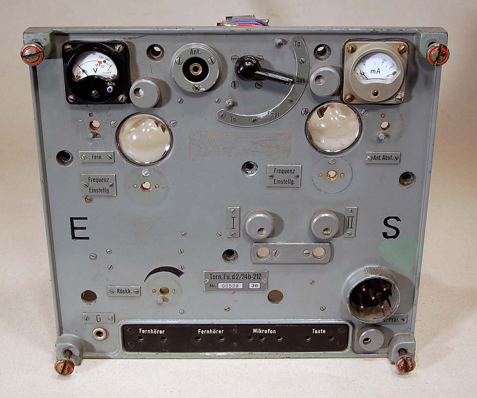
Torn.Fu.d2 with front
cover mounted.
This Torn.Fu.d2 is
produced in 1936 with the latest tube technology available.
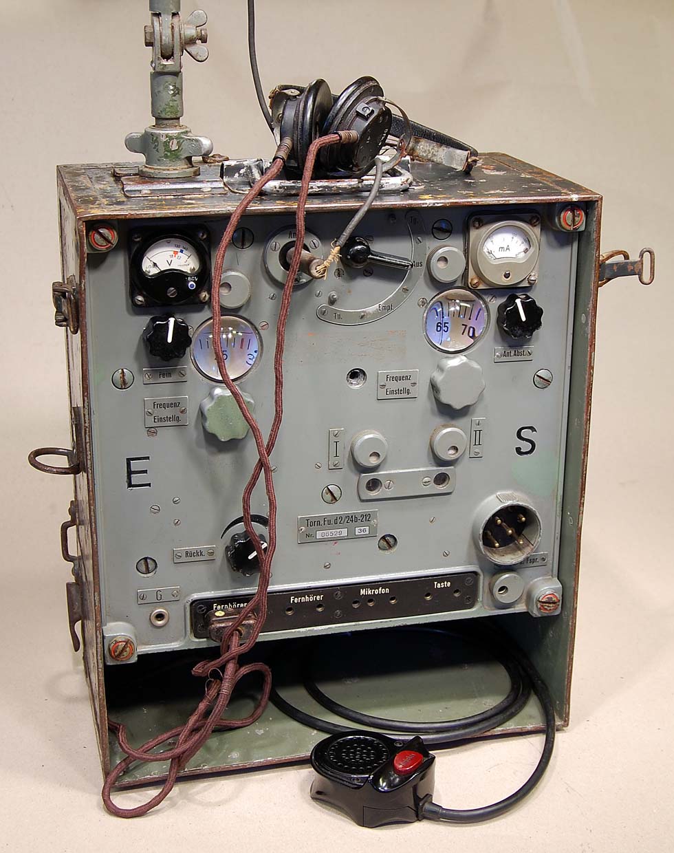
| General info from the
handbook: This portable transceiver Torn.Fu.d2
is a VHF 2 way communications device with |

LA8AK’s
block diagram.
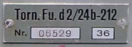
| Torn. Fu. d2 Portable VHF tranceiver Frequency range: 33.8 - 38.0 MHz Tx output Power: 1 Watt IF = 2.1 MHz. Power: 2.0V - , 130V - Measures: H = 390 mm, W = 340 mm, D = 190 mm Weight: 17 kg |
Front panel with all
electronics removed.
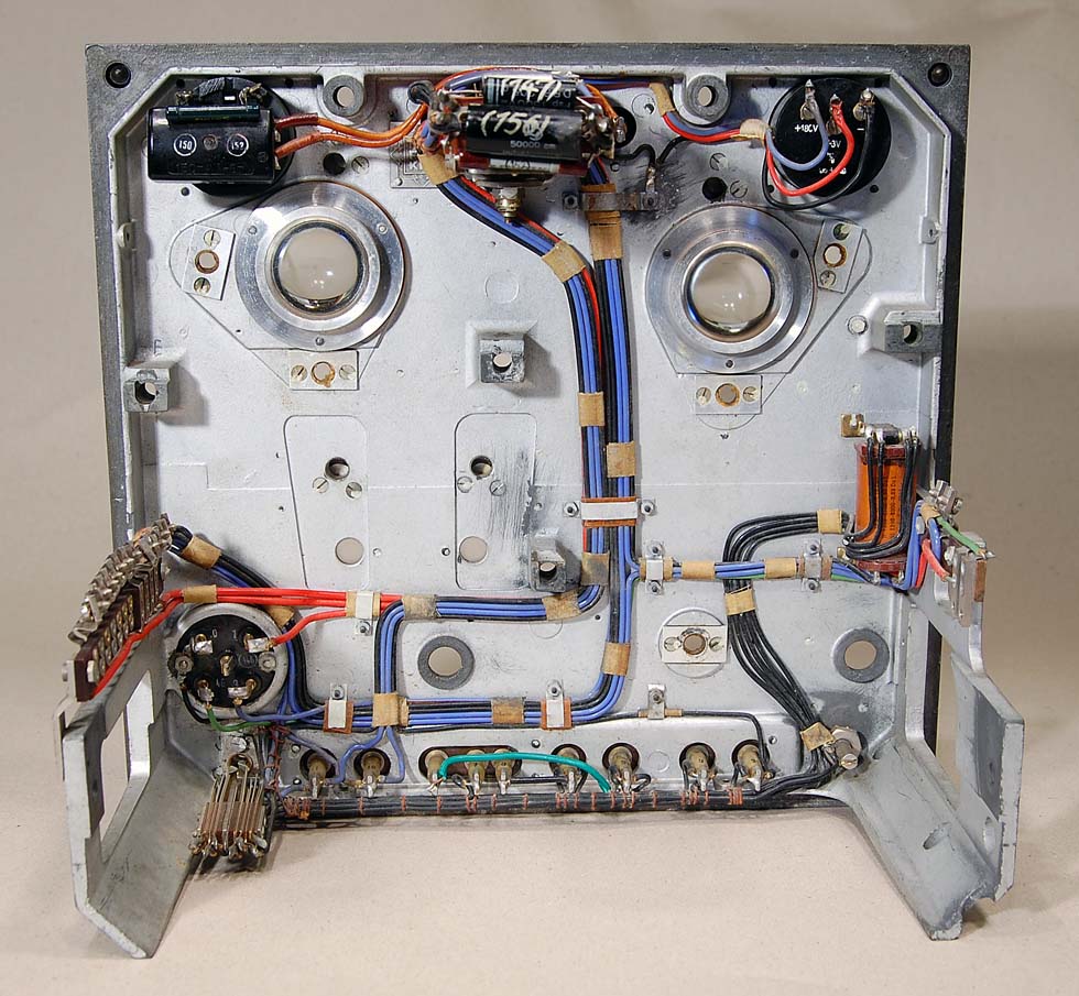
Inside front panel. Very
nice work with the cables.
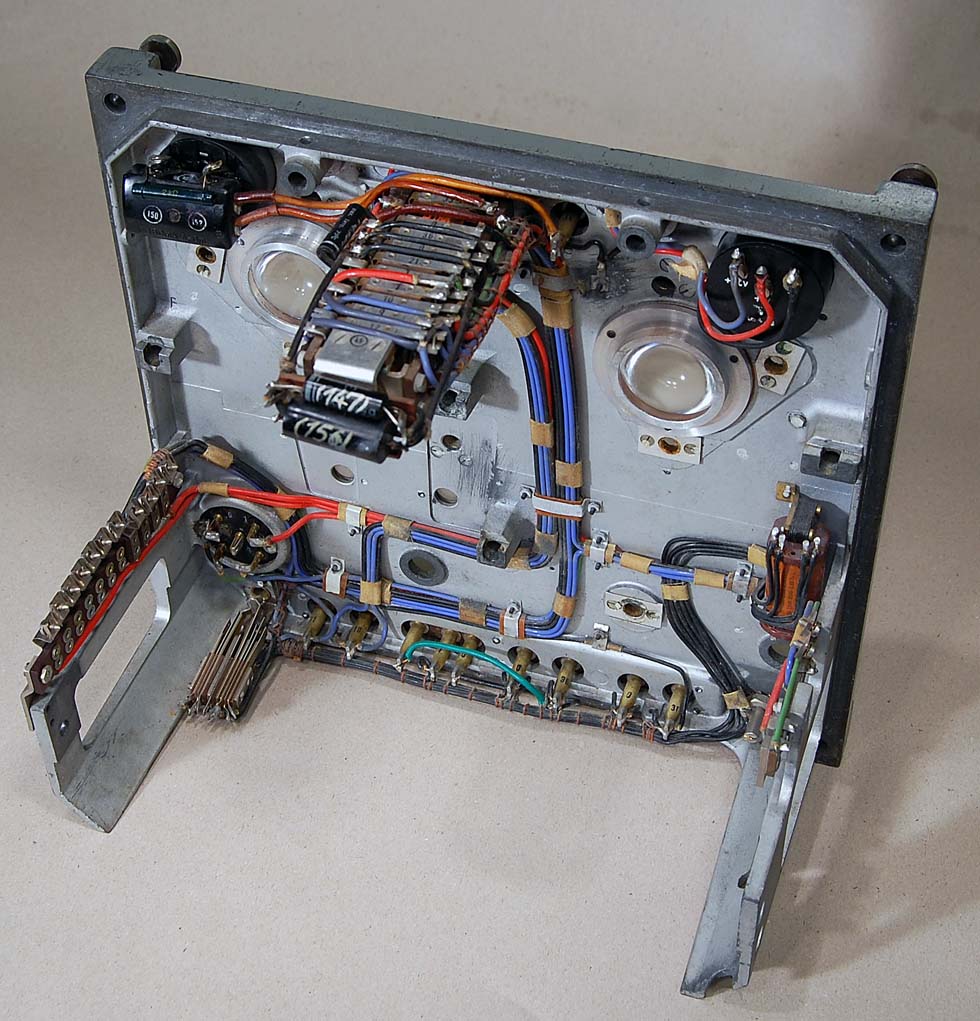
Each of the modules can
easily be removed from the frame.
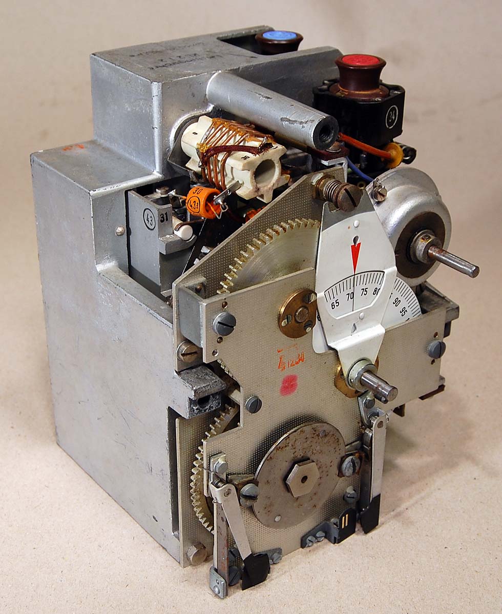
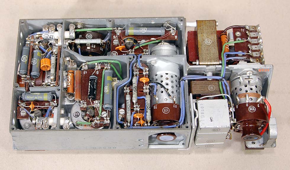
RECEIVER
Here is the receiver
module with the frequency tuning mechanism in front.
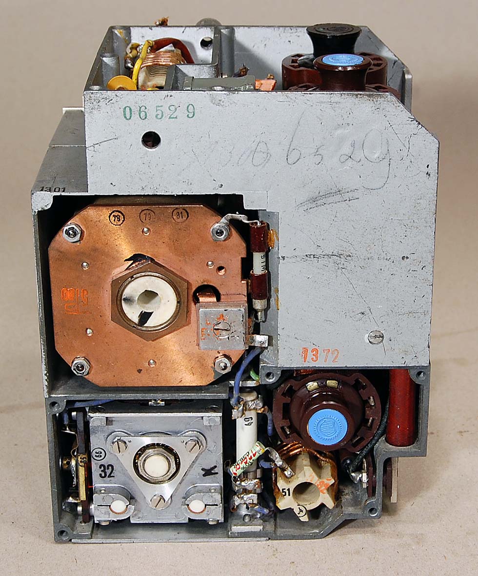
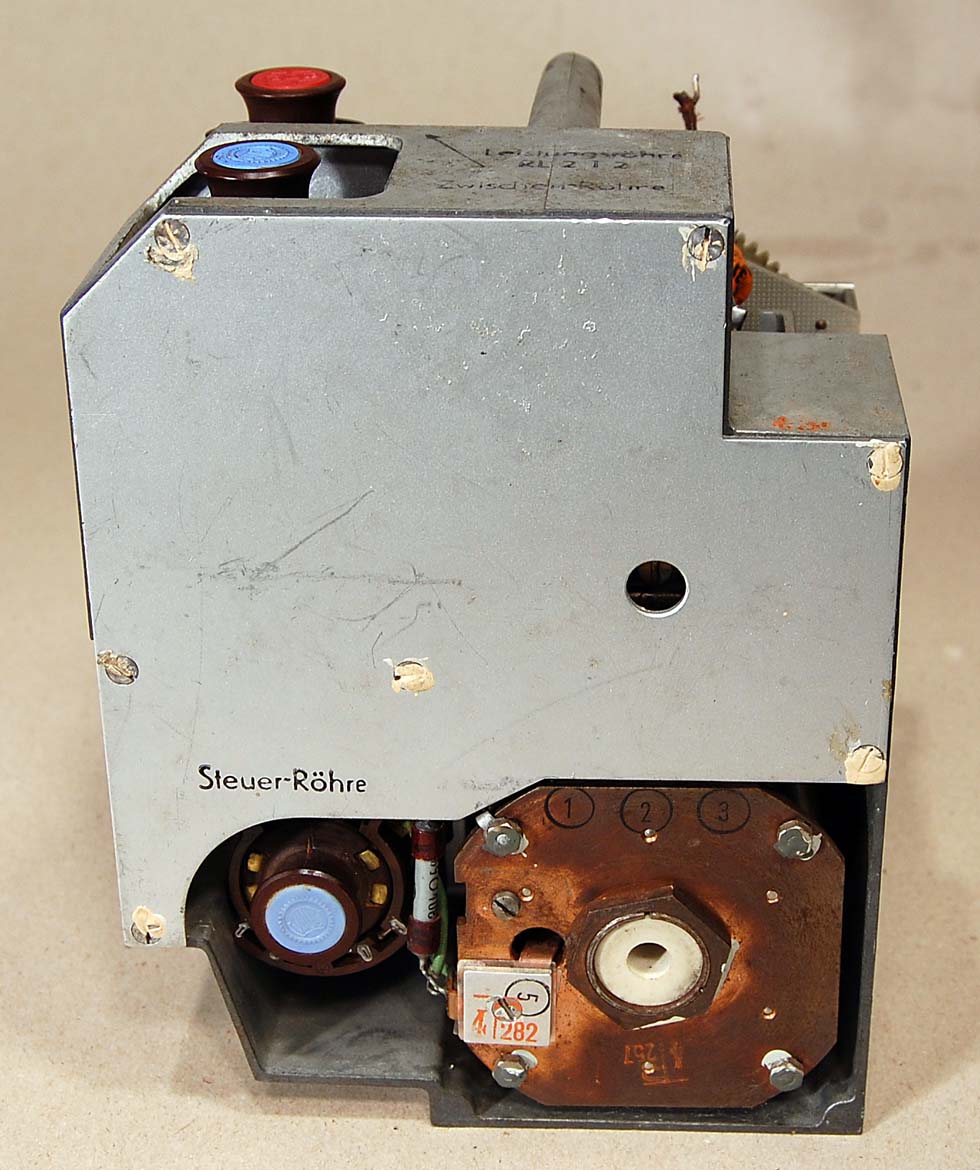
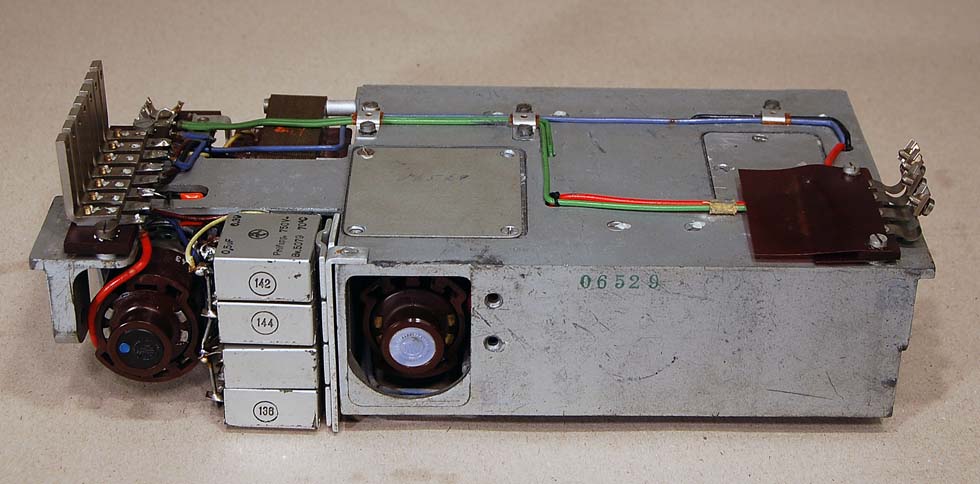
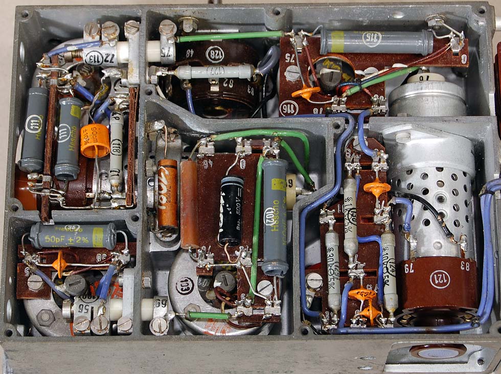
| The rear of RX module. Bottom left is the tuning capacitor. Top left is the oscillator cavity. Bottom right is the oscillator tube RV2P800. |
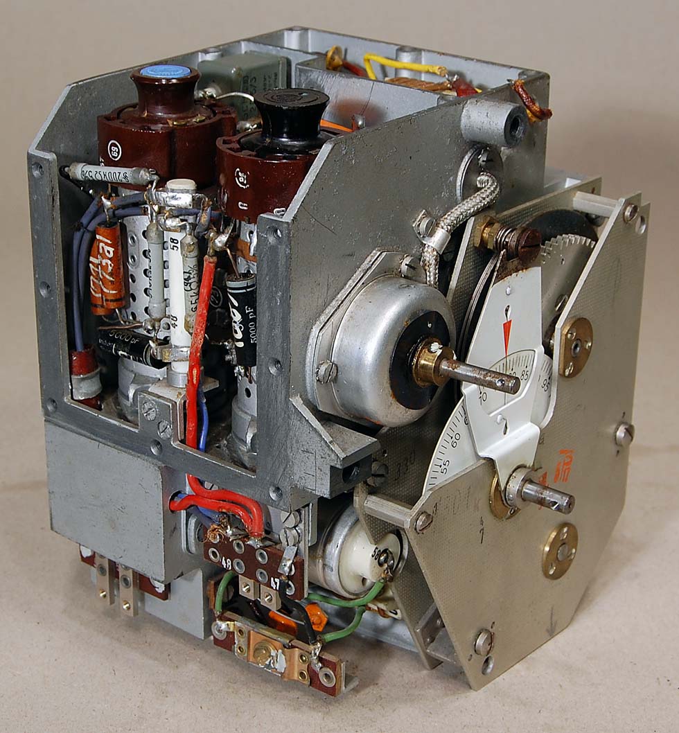
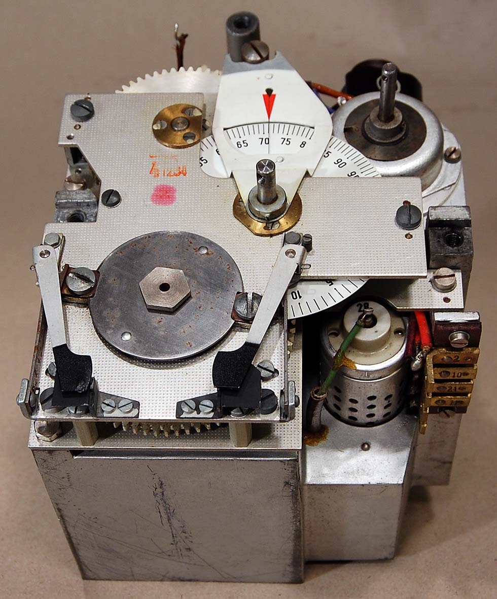
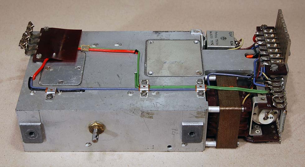
| Left view of the receiver
module. From left: Mixer tube RV2P800 and RF input tube RV2P800. Bottom left is the MF output terminals form the mixer. |
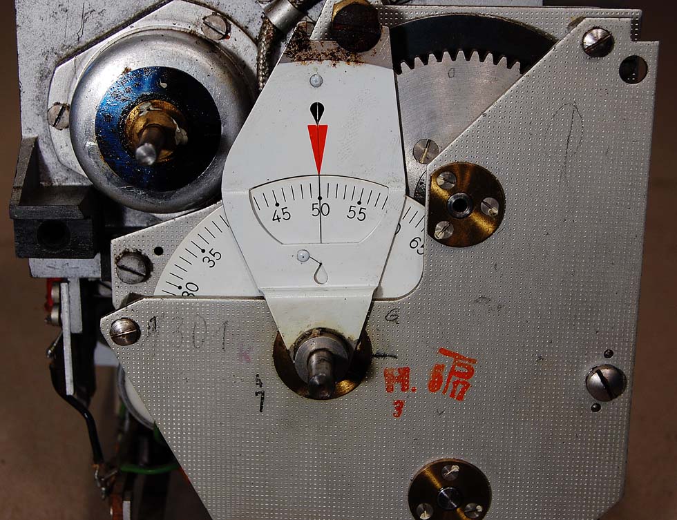
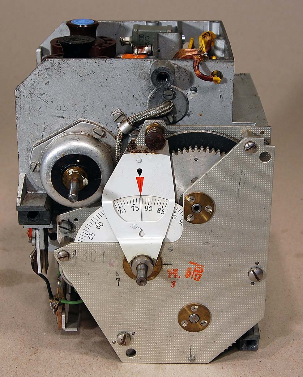
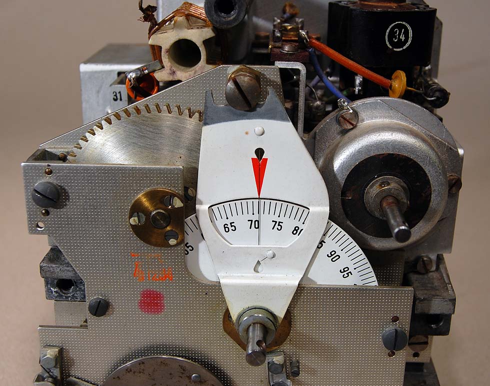
Here is the RX tuning
dial. Bras bearings is used on all axels.
TRANSMITTER
MF & LF
Frequency
Generator in transmitter and receiver in Torn.Fu.d2
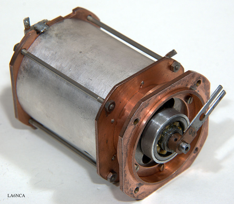
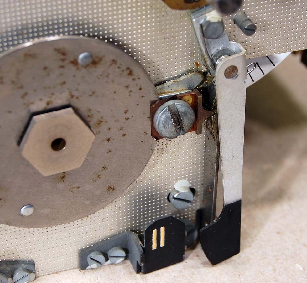
| This is an absolutely
fantastic component. This unit determines the frequency of the transmitter and receiver in Torn.Fu.d2. This is the finest LC circuit I've seen. This unit contains the entire oscillating circuit of the oscillator. |
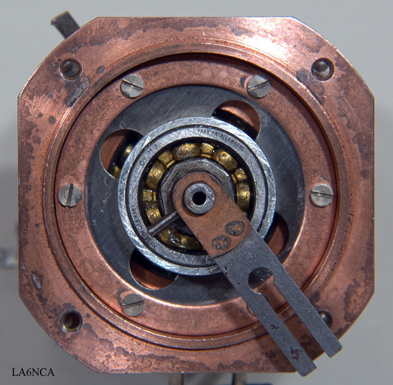
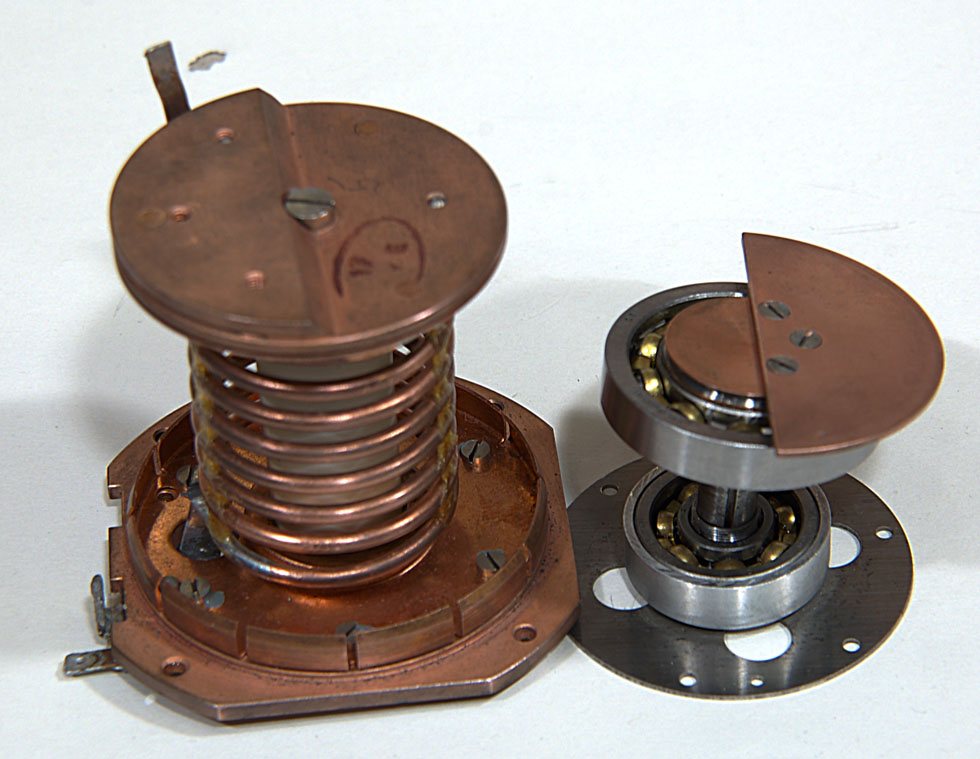
Two SKF ball bearings makes the mechanical accuracy absolutely
prefect.
a4a.jpg
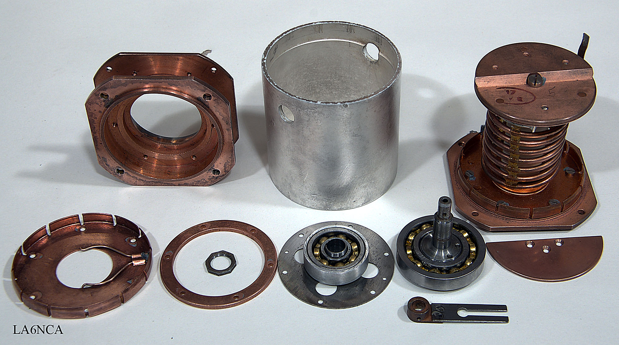
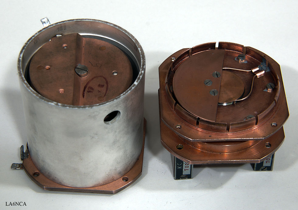
Here are all the parts. The
cylinder is made of silver plated metal.
All the brown parts are made of copper.
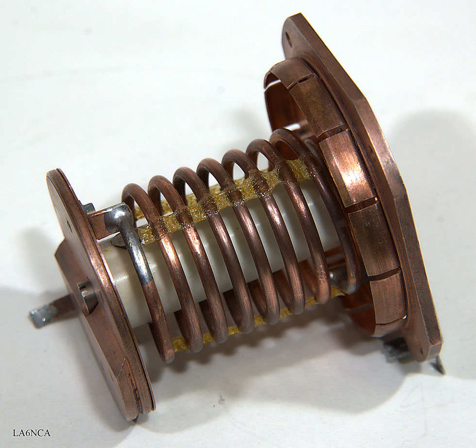
Here is the fantastic fine coil.
| The brown plate to the left
is connected to the top of the coil. Plate to the right rotates and forms a variable capacitor toward the plate to the left. This being a resonant circuit with super high Q. |
Here we see both the coil and capacitor in the oscillating
circuit.
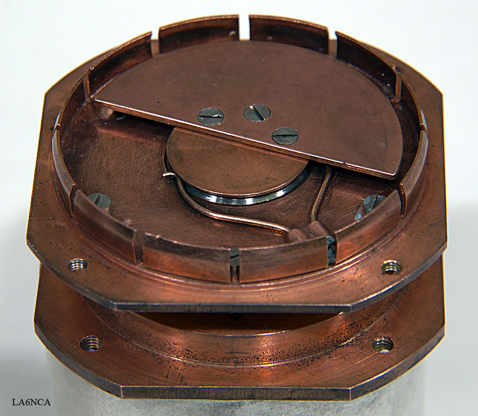
Closeup of the capacitor rotor. It is connected to GND.

The bearings are made of SKF and is very accurate.