 |
LA6NCA RADIO PAGE Torn.Fu.b1, Torn.Fu.f |
 |
|
LA6NCA RADIO PAGE Torn.Fu.b1, Torn.Fu.f |
|
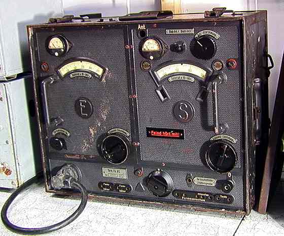
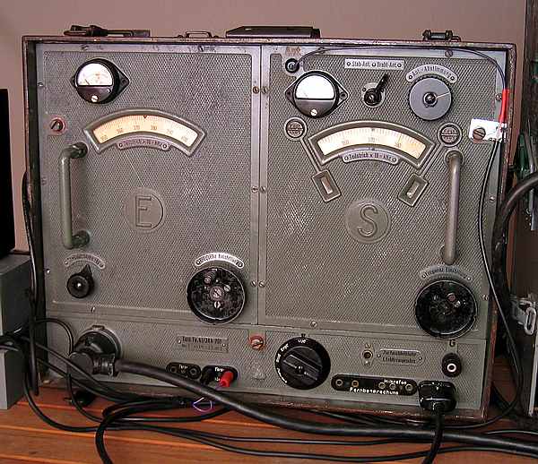
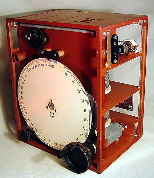
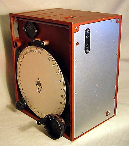
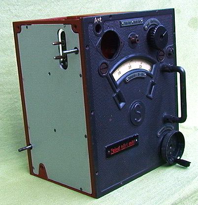
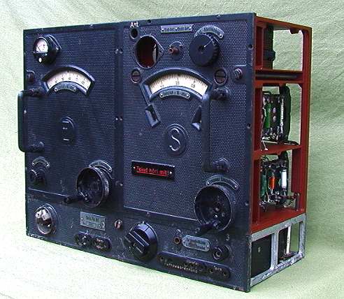
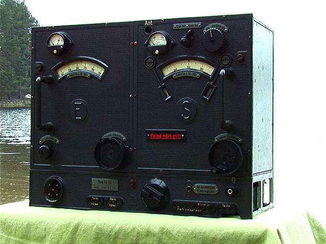
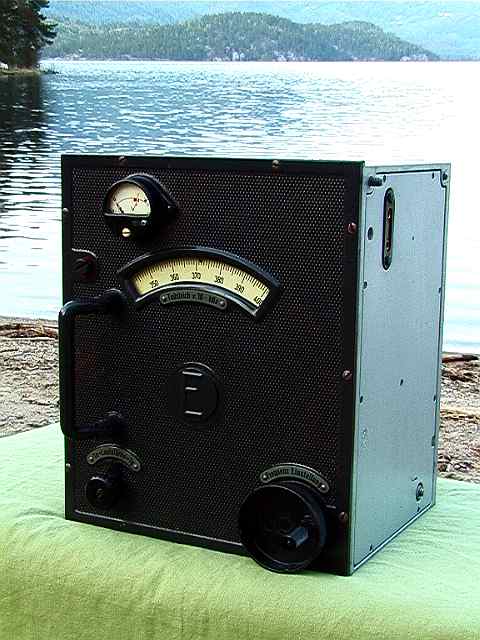
This is a
portable field transceiver used by the German army.
Frequency range in MHz:
| Type | Transmitter | Receiver |
| Torn.Fu.b1 | 3.0 – 5.0 | 3.0 – 6.66 |
| Torn.Fu.c | 1.5 – 2.3 | 1.5 – 2.6 |
| Torn.Fu.f | 4.5 – 6.66 | 3.0 – 6.66 |
| Torn.Fu.b1 was developed by Lorenz in
1935/36. Output power is 1 Watt. Modulation is A1 and A3. Total weight with accessory box is 20 kg. Tube used is RV2P800 and one RL2P3 in the transmitter. |
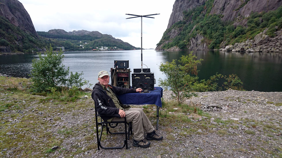
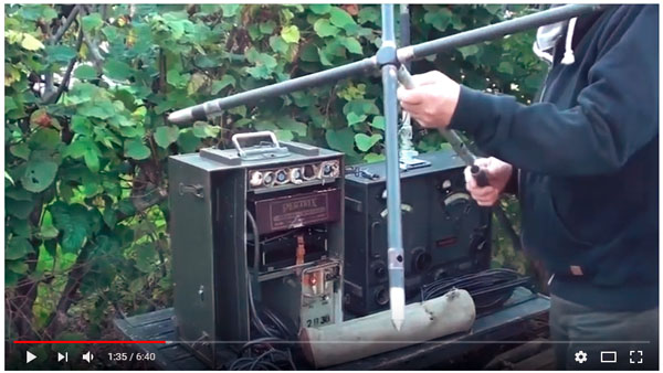
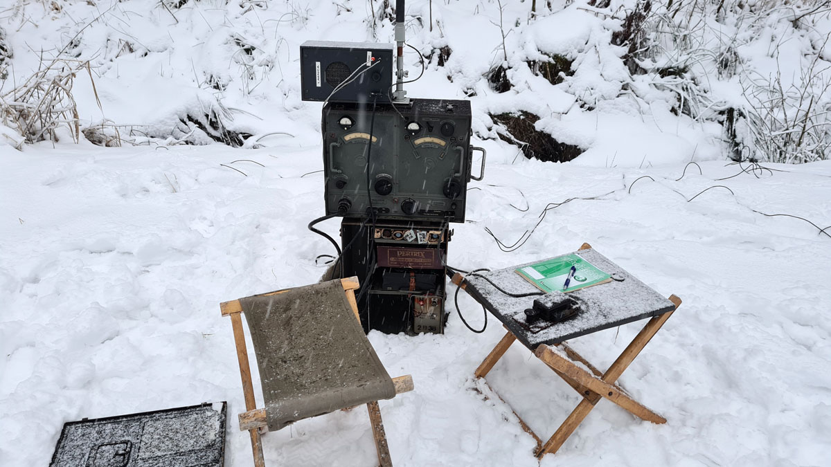
| I have now installed my
Torn.Fu.b1 equipment in Jøssingfjorden. This is a historic place. This was where WW2 started in Norway. |
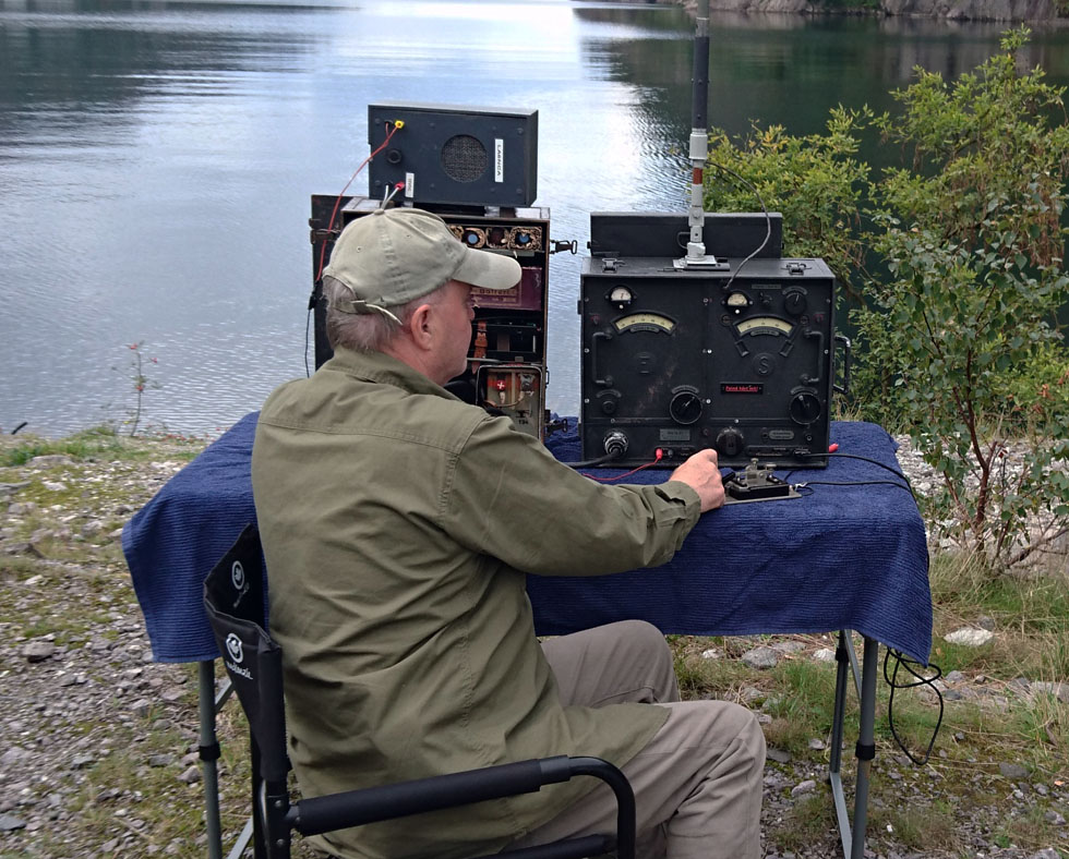
| I have now contacted LA9IAA
in Larvik. It is very good. It is a distance of 232 km. I had to plug on a 15 meter wire on the antenna. I was unable to connect with the little antenna on the radio. |
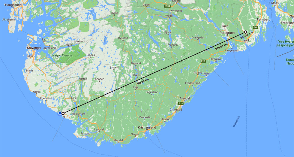
Here we see the map of the connection. Fantastic at 1 watts.
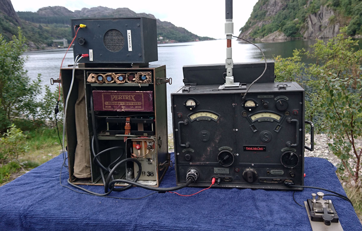
Here we see the equipment. I had to connect to a ground plane
before I could use the radio.
Film, CW QSO with originale antenna.
Film, Torn.Fu.b1. connected to a FF33
telephone.
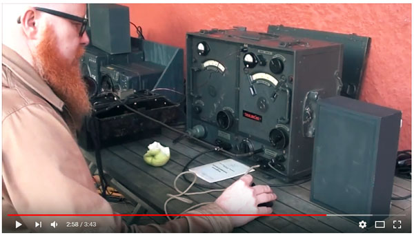
| Field test of Torn.Fu.b1.
QTH is near Seljord in Norway. Very good CW signals vas received in Halden and Bergen. The output power is only 0.8 Watt. The Torn.Eb is used for side-tone and netting (Tx and Rx synchronisation). The Fu.H.E.c is used for receiving 20 and 15-meter ham radio band. |
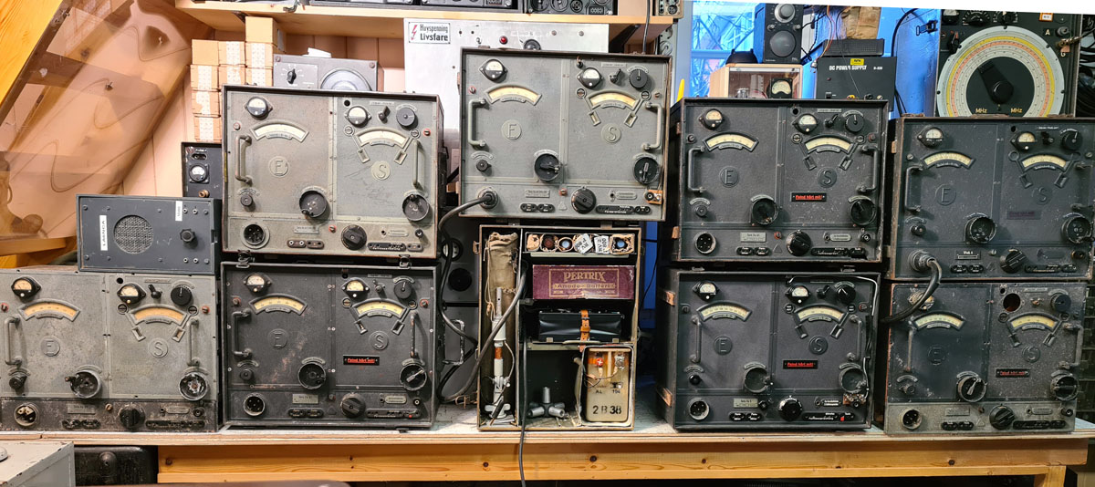
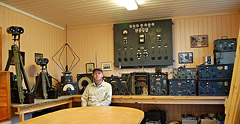
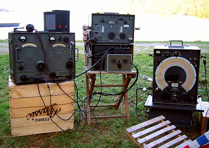
My collection of operational radios.
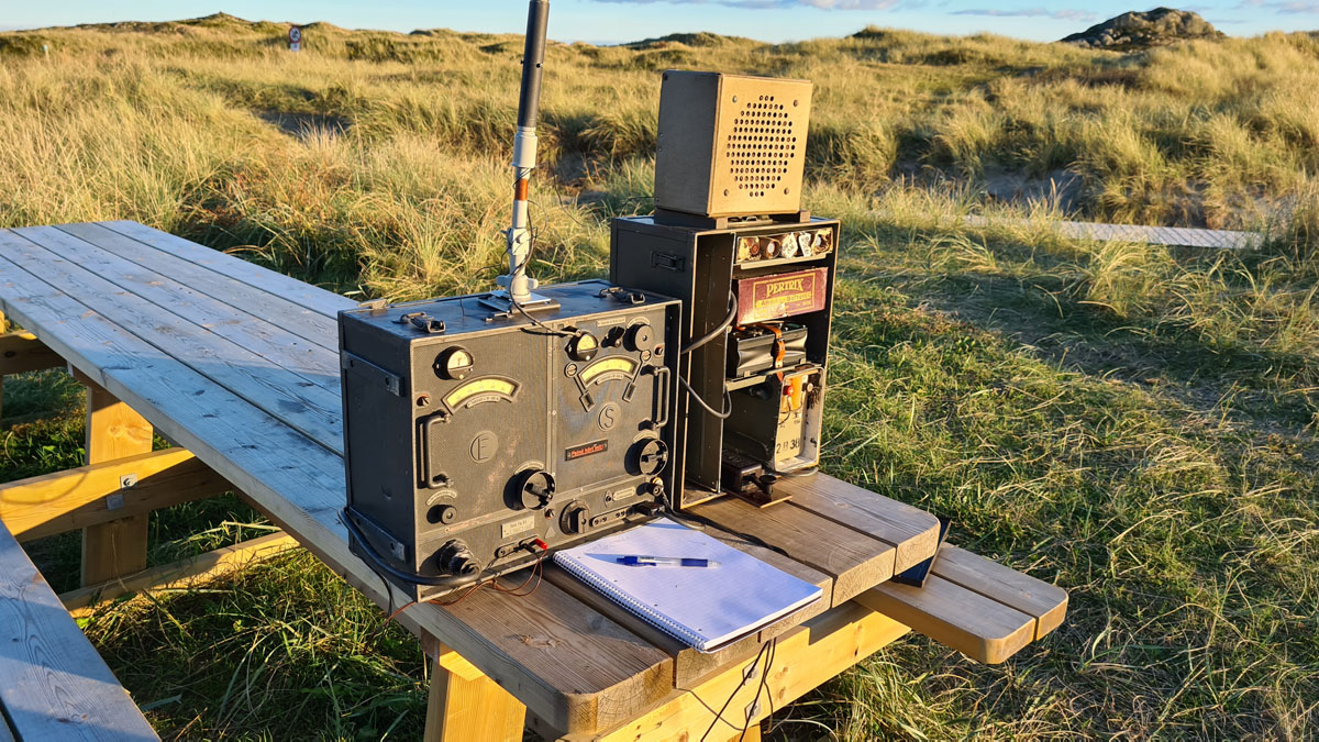
I have set up a transmitting station on Lista beach, Havikstrand.
It is evening and the sunset illuminates the radio.
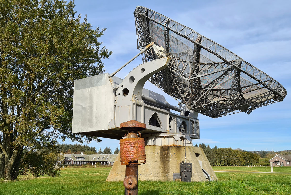
Torn.Fu.b1 mounted during a Würzburg-Reise on Lista. In the
background
is the original officers' fair at the German airport on Lista.
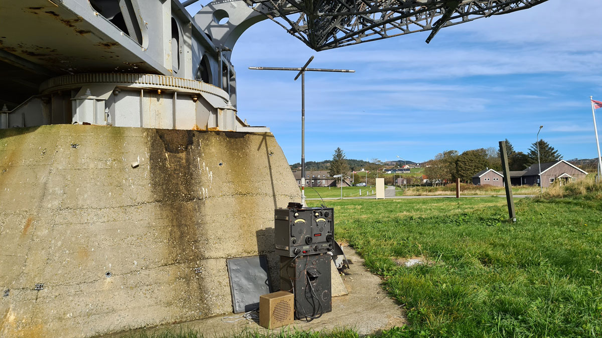
Würzburg-Reise is an impressive construction.
http://www.festunglista.com/
I test how it works in snow.
It passed the test.
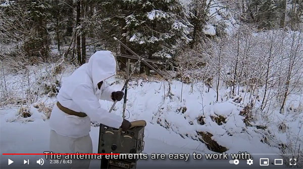
My video in snow.
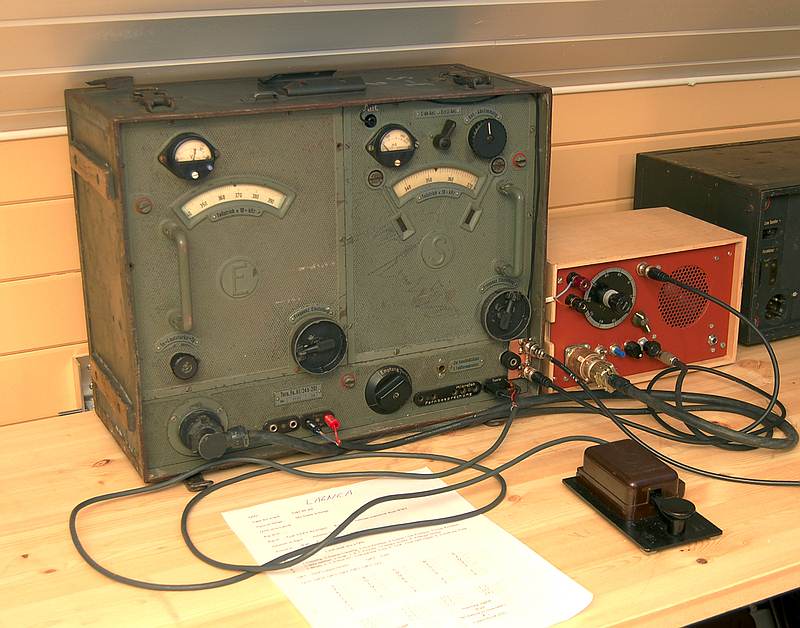
Here's another Torn.Fu.b1 with my homemade side tone box.
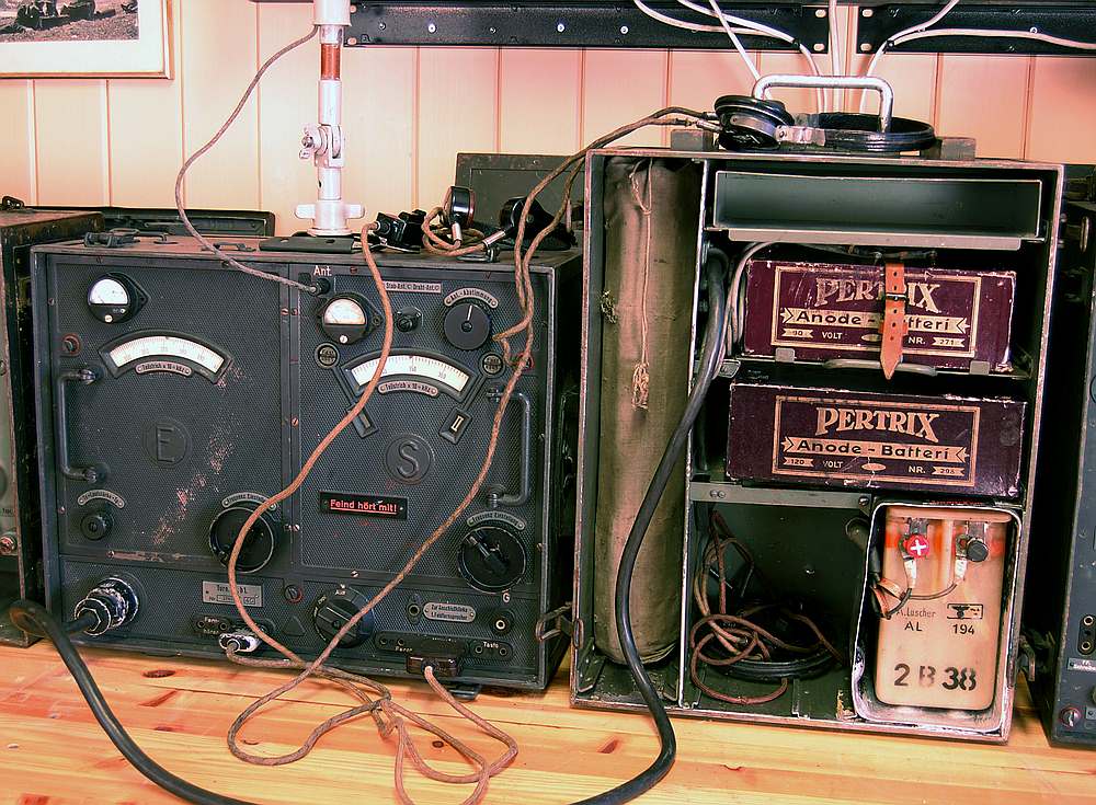
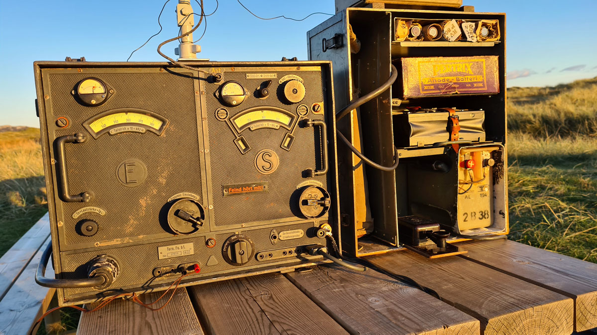
Torn.Fu.b1 with the original battery box.

| Torn.Fu.b1 used for
communication in the 80-meter ham band. Torn.Fu.B1 have no sidetone and no netting is possible. Torn.Eb is used for this. I have designed a control box for switching antenna and audio signals (left). This box has tree functions. Position 1 – Torn.Fu.B1 is used as a transceiver. Torn.Eb is used as a side-tone generator. Position 2 – Torn.Fu.B1 is connected to a 50 ohm resistor. Torn.Eb is used as a receiver. Position 3 – Torn.Fu.B1 and Torn.Eb antenna connectors is connected together. Position 1 – Operation. Position 2 – Calibration of the transmitter frequency. Received zero beat in Torn.E.b. Position 3 – Calibration of the receiver frequency. Leakage from Torn.E.b’s oscillating detector is received in the Torn.Fu.b1 receiver. |
Field
operation of Torn.Fu.b1
This is some of what had to be done to get Torn.Fu.b1 field
operative.
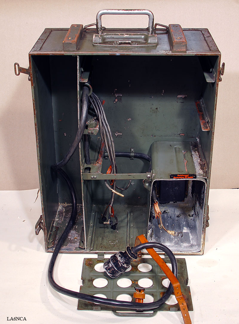
This is closeup of the
empty battery, and equipment box.
This is all the wires that were connected to the battery.
I must now create a power that supplies the required voltages
Here I mount my Torn.Fu.b1 power on the mounting bracket. .
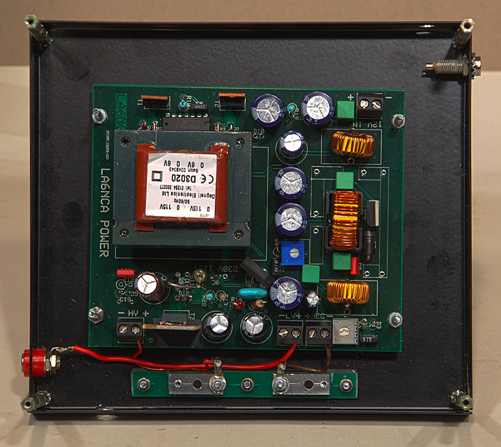
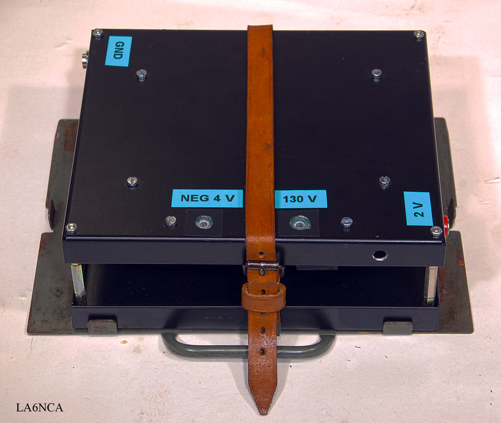
| Here is my power
for Torn.Fu.b1 It has 12 volts DC input. Output is 2 volts to the tubes. -4.5Volt for grid voltage. + 140 Volt for anode voltage. It has exactly the right size to fit into Torn.Fu.B1's battery box. I've made small connectors that battery cables of Torn.Fu.b1 fits. It is 3.6 mm holes that fit connectors of Torn.Fu.b1 |
ANTENNA
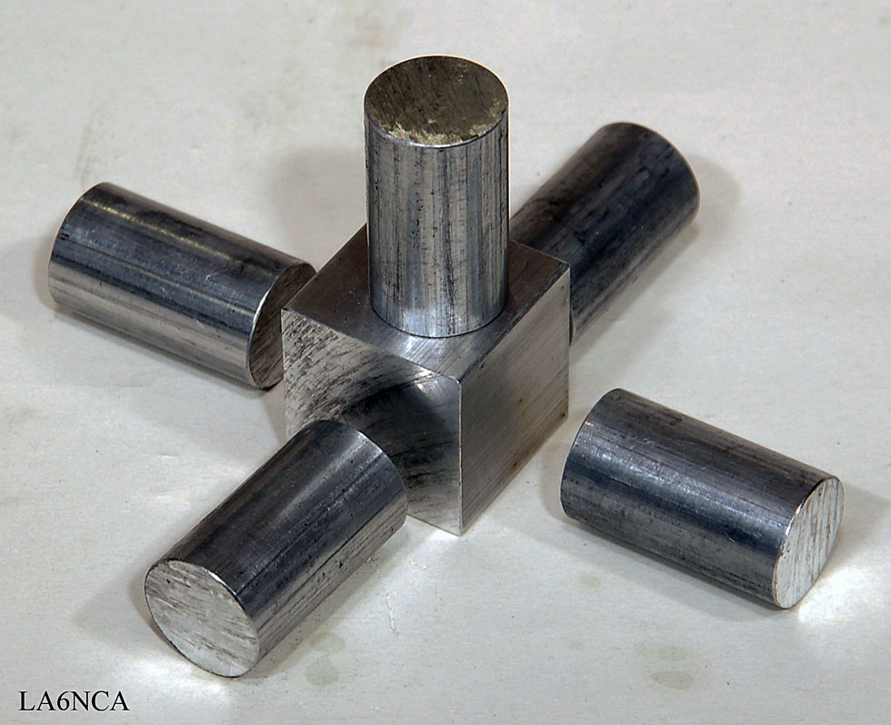
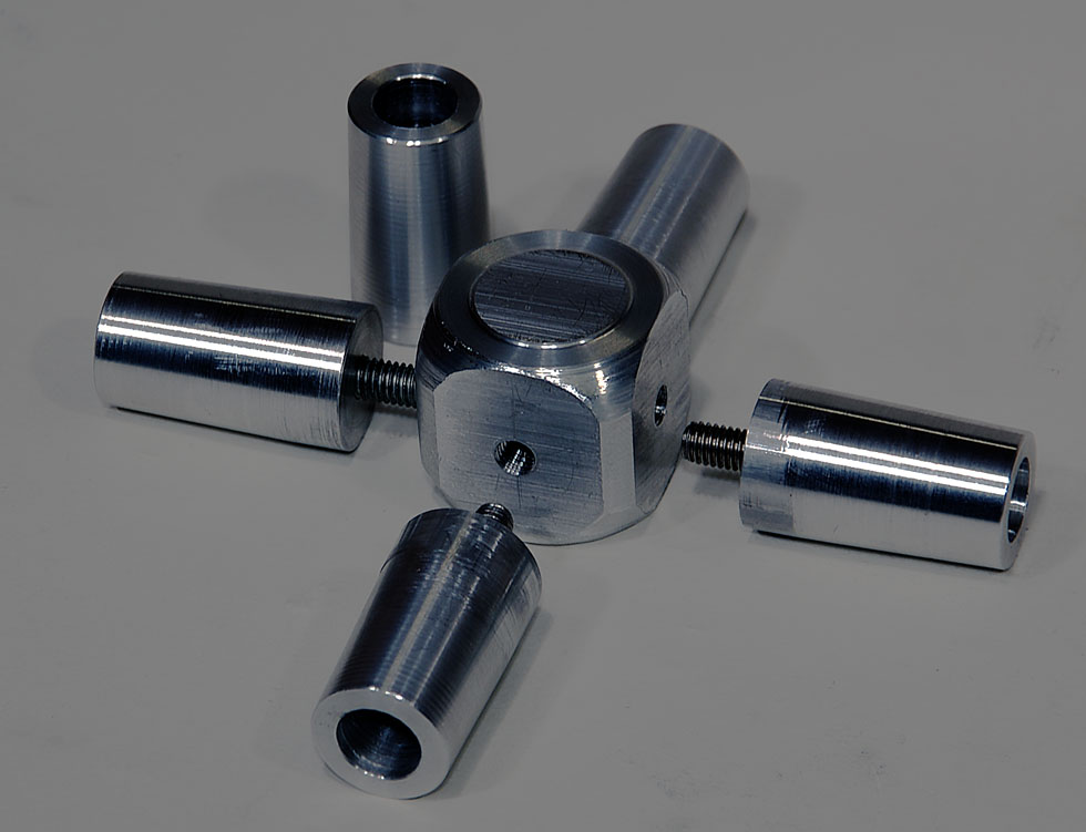
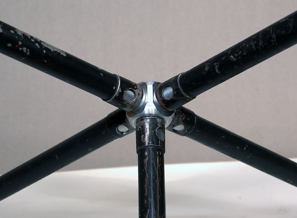
| Antenna cross
section. I have started to make a copy of this. |
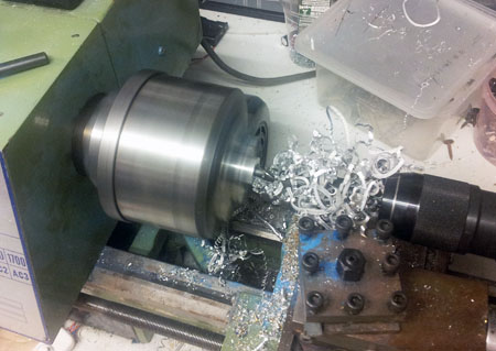 step 1 Drill a 10mm or 12mm holes with depth 20mm. |
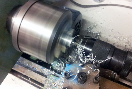 step 2 From the other side I drills a 6mm hole until it comes out in the large hole. |
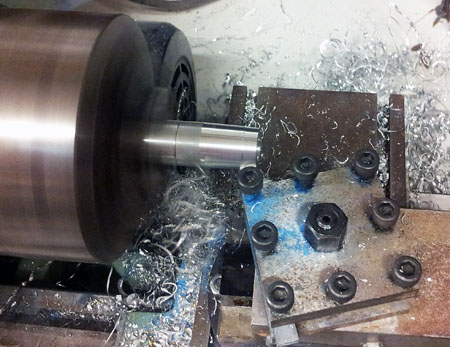 step 3 The rod is screwed with a 6mm screw to an identical rod which is fixed to the machine. Sets the angle of 1 degree. Machined- down so that the entire length the bolt is machined. The largest diameter is thus still 20mm. |
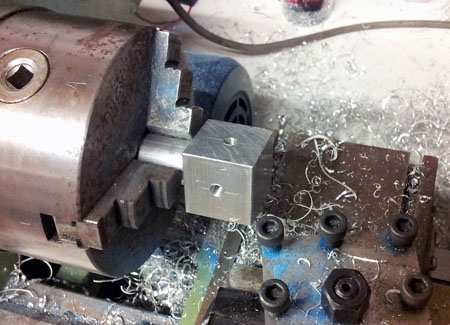 step 5 Here is the aluminum cube mounted with a 6mm screws to a 20mm aluminum rod that has 6mm threads. |
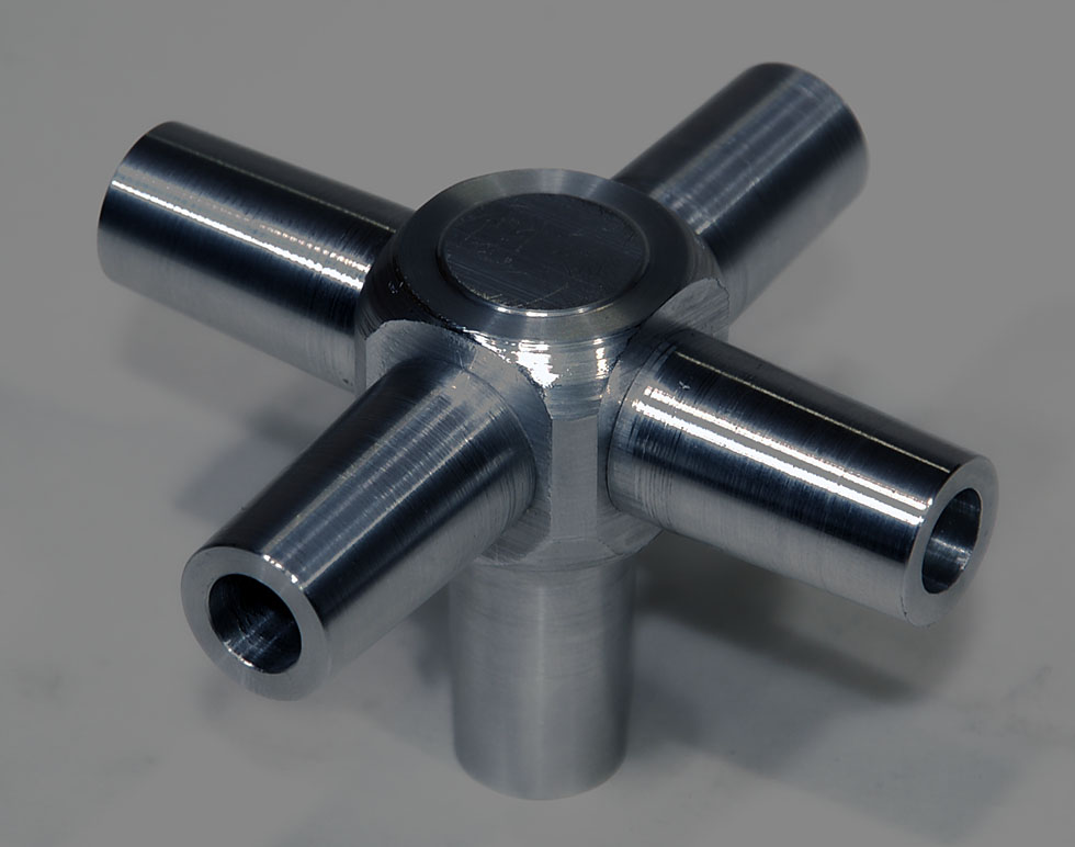

Here we see the fantastic casting technique used.
The upper and lower parts are taken apart.
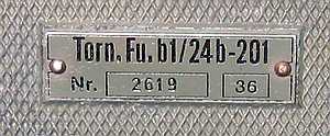
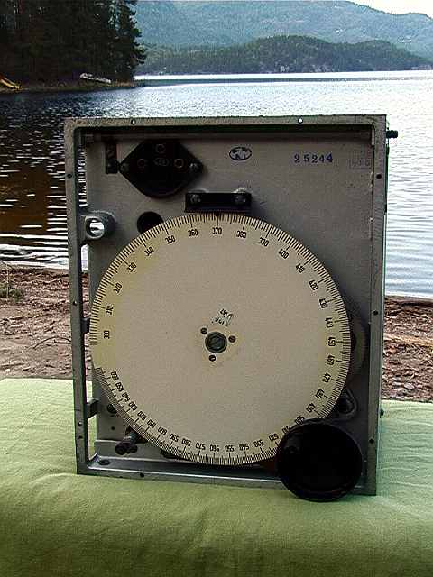
tornfu46a.jpg
Torn.Fu.b1 /
24b-201
no. 5, serial no. 2619, year 1936
This is a
portable field transceiver used by the German army.
Frequency range in MHz:
| Type | Transmitter | Receiver |
| Torn.Fu.b1 | 3.0 – 5.0 | 3.0 – 6.66 |
| Torn.Fu.c | 1.5 – 2.3 | 1.5 – 2.6 |
| Torn.Fu.f | 4.5 – 6.66 | 3.0 – 6.66 |
| This transceiver
was developed by Lorenz in 1935/36. Output power is 1 Watt. Modulation is A1 and A3. Total weight with accessory box is 20 kg. Tube used is RV2P800 and one RL2P3 in the transmitter. |
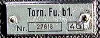
no. 1, serial no. 27618, year 1940
 1
1
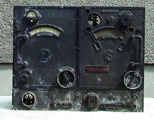
| This one is in very bad
condition when I received it. Everything is stuck, and there is much corrosion. The picture was taken before restoration work. |
 2
2
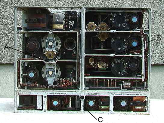
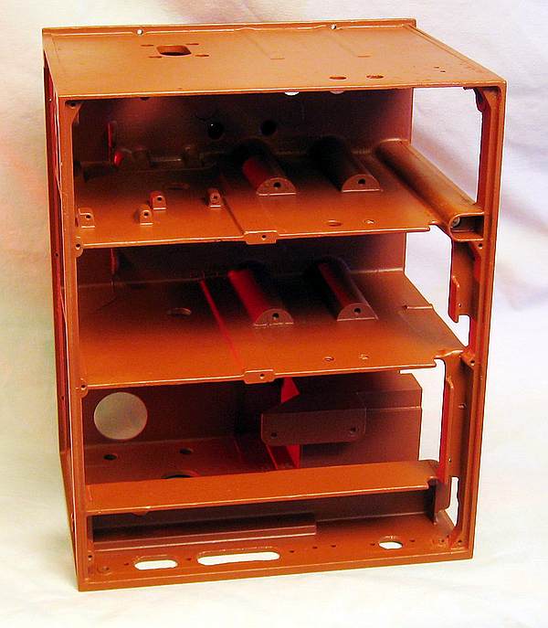
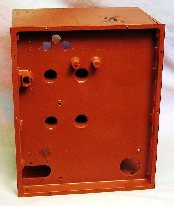
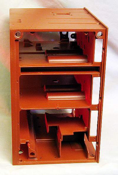
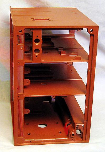
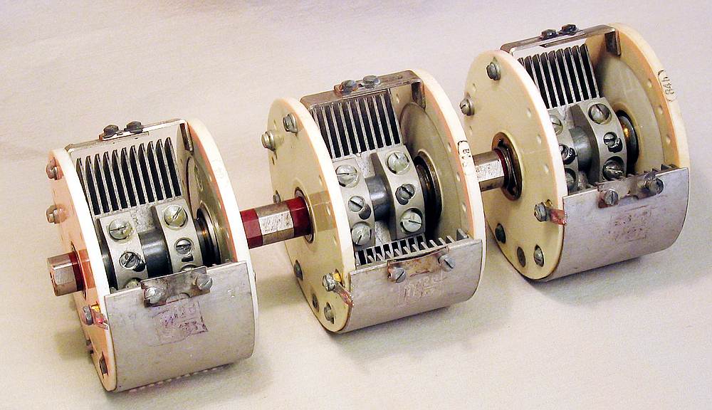
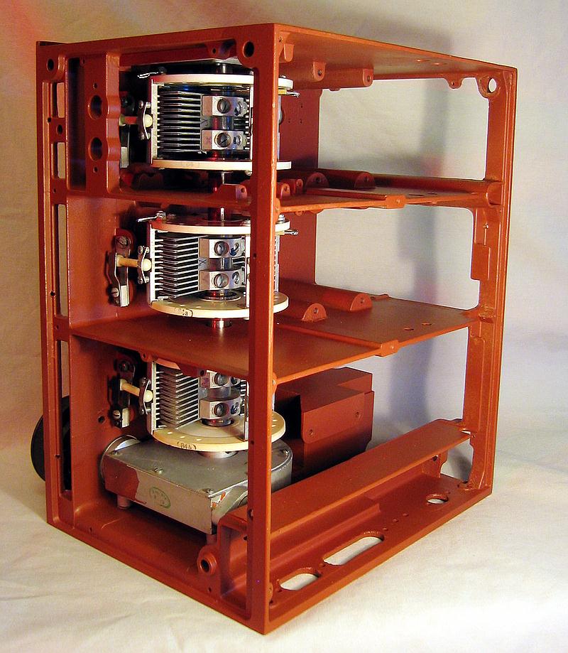
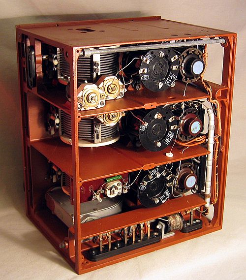
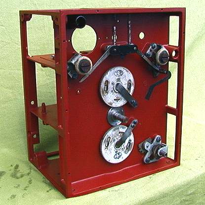
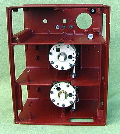
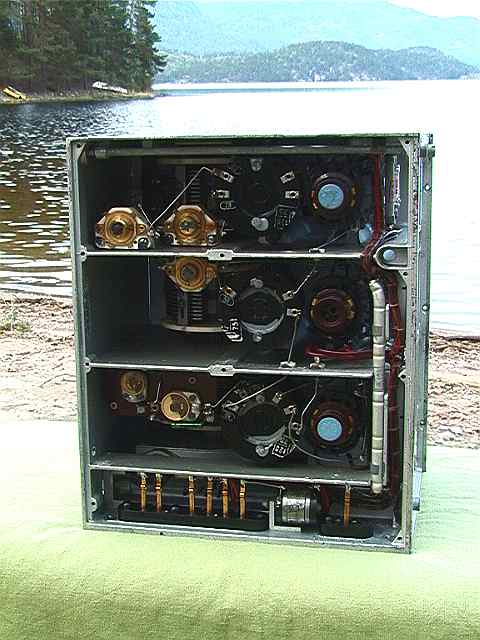
The radio is built up
like building blocks.
(A) - Transmitter, (B) - Receiver, (C) - Audio amplifier.
TRANSMITTER
 3
3
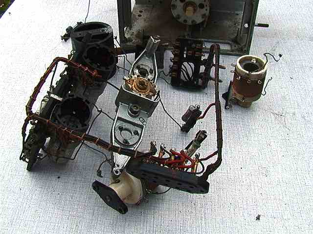
Here is all the
electronic removed from the chassis.
 4
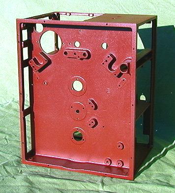
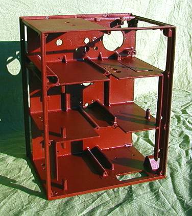
4
Here is all the corrosion removed from the chassis. The chassis
have also new paint.
 5
5
 --
-- 
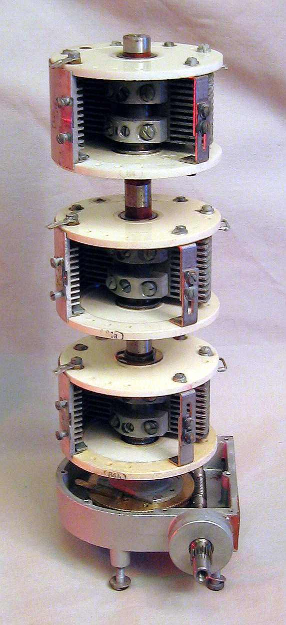
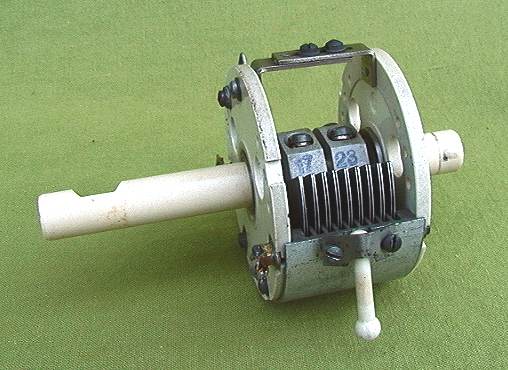
This is the condenser to the receiver.
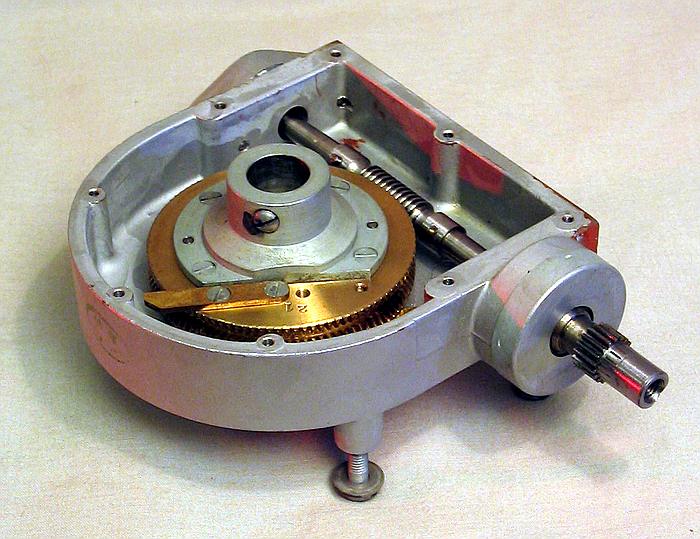
At the bottom, this fantastic fine gearbox.
Here are receiver capacitor removed from the gearbox.
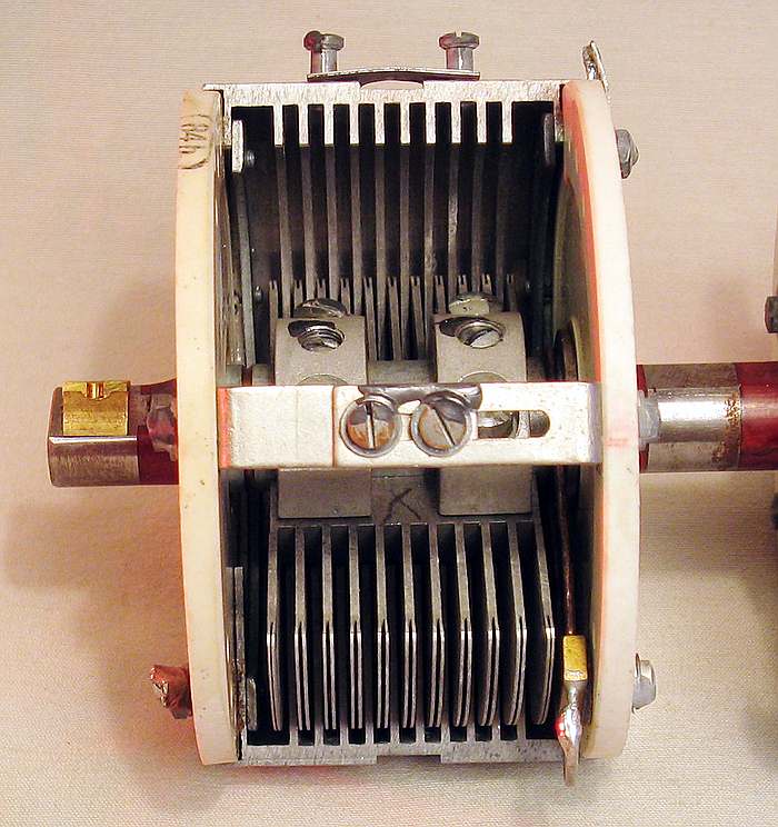
Close up of one of the sections. Highly accurate machining work
is done.
The stator is held in place with a porcelain part left of the
picture.
The stator is supported on the capacitor shaft.
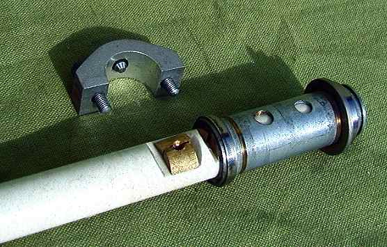
| Here are the receiver
capacitor mounted in the mechanics. Here we can see the porcelain pieces that hold capacitor stator. This is a unique design method for making radio frequency stable. |
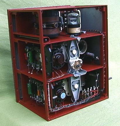
Have installed all the electronics of the receiver.
Have installed all the electronics of the receiver.
The receiver is here completely finished.
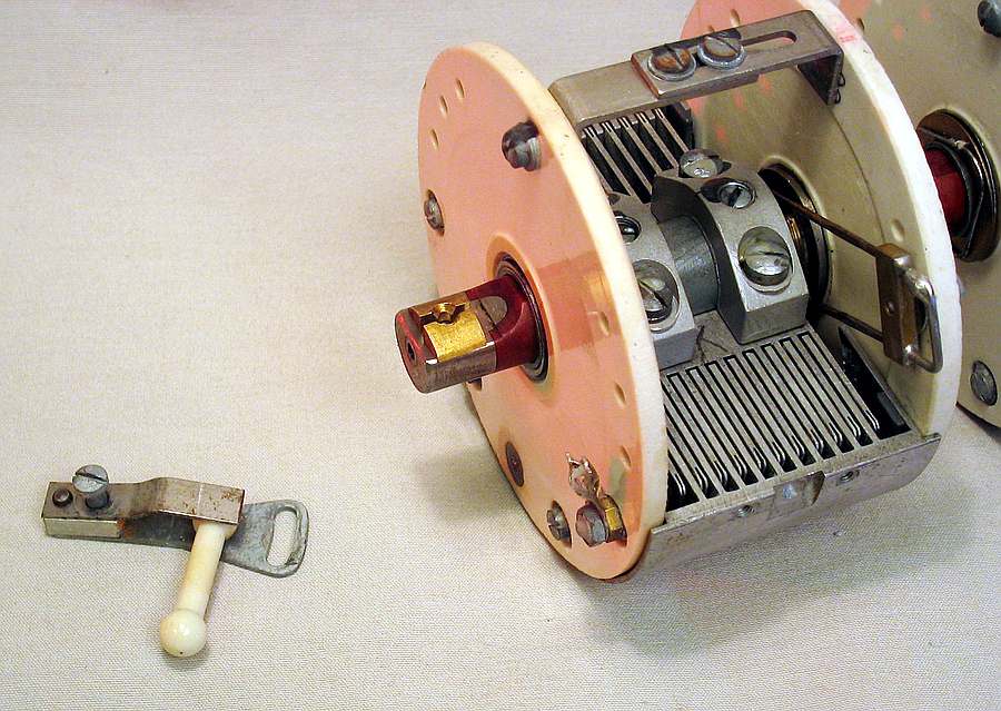
CAPACITOR
 6
6
| The capacitors were stuck,
so they had to be completely dismantled. This is the capacitor that was used on many that the German radios. This is one of the most accurate and impressive the details of the radio. The condenser is mounted on a ceramic shaft. The stator is mounted on the shaft. Ceramic rod with ball ends provide stable attachment to the mechanics. |
 7
7
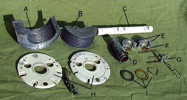
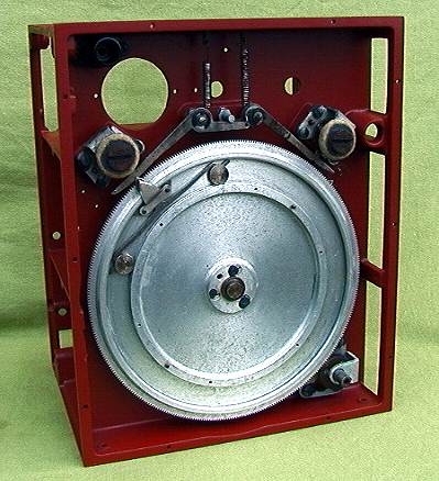
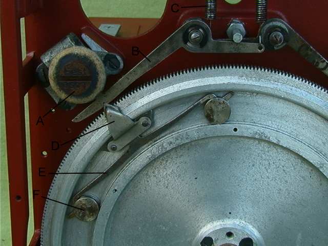
| Here is the entire condenser
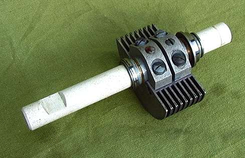
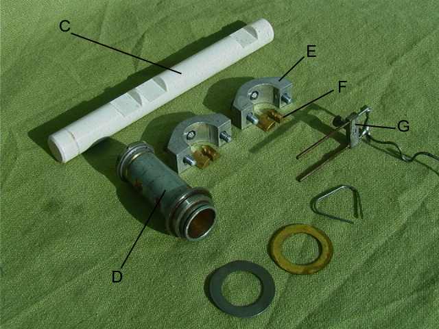
dismantled. (A) - Stator. This is milled out of a large block of aluminum. (B) - Rotor. This is machined by a large aluminum shaft. (C) - Shaft. Ceramic shaft for insulation of the rotor. (D) - Rotor Bearing. Made of brass and steel rings. (E) - Mounting brackets for rotor. (F) - Attach Bits for ceramic shaft. (G) - Connectors for the electrical connection to the rotor. (I) - springs and rings to create constant pressure on the stator. (H) - Porcelain discs that make up the condenser bearing and end cap. |
 8
8
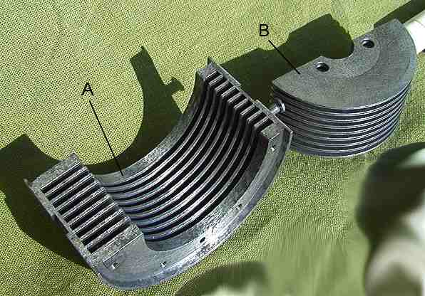
| (A) - Stator. Here is a
close up of the stator. Here we see the logarithmically increasing disc space to create a linear frequency scale. (B) - Rotor. |
 9
9
Rotor with porcelain
shaft.
 10
10
Fantastic
sophisticated mechanics in the condenser.
 11
11
Here is a close up of
the rotor shaft and bearings.
 12
12
| Here are the mechanical
details started to come into place. It is a very demanding task to dismantle and build up such a radio. All connections and wires were documented before disassembly. Many advanced mechanical settings must be made during rebuilding. |
Here are the mechanics
of the frequency scale in place.
 14
14
The transmitter has
two pre-programmable frequencies.
 15
15
Transmitting
capacitors are set in place.
 16
16
The entire transmitter
is mounted.
 17
17
The transmitter seen
from the front.
 18
18
Torn. Fu. b1
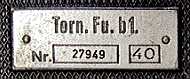
no. 2, serial no. 27949, year 1940
Receiver section with rf-stage, oscillator and mixer.
Behind the front plate.
Very accurate tooth
well is used inside. Double wheel with spring is used for
removing backlash.
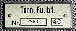
Torn. Fu. b1
no. 3, serial no. 27603, year 1940