|
LA6NCA
RADIO COLLECTION |
|
|
LA6NCA
RADIO COLLECTION |
|
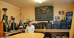
| This is
a high quality HF receiver used in Luftwaffe and
Kriegsmarine. Created by Lorenz in 1942. Frequency range from 1.5 to 25 MHz. This receiver was LORENZ's competitor to TELEFUNKEN's E52 Köln. Only 1000 of this radio was produced. This is one of the "big" receivers that are produced during WW2. |
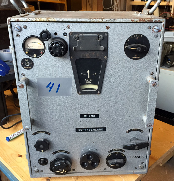
How it looked when I bought it.
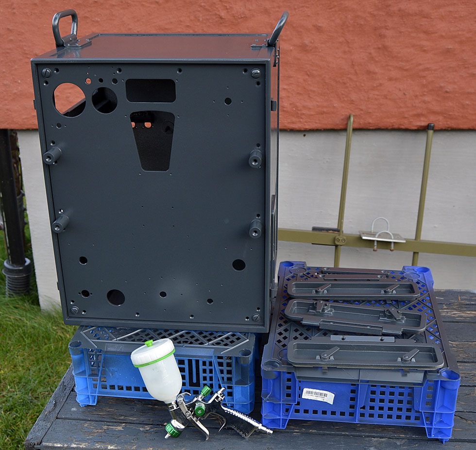
I had to get away the terrible hammer paint.
Has here painted with RAL7016.
sw21a.jpg
sw22a.jpg
sw9a.jpg
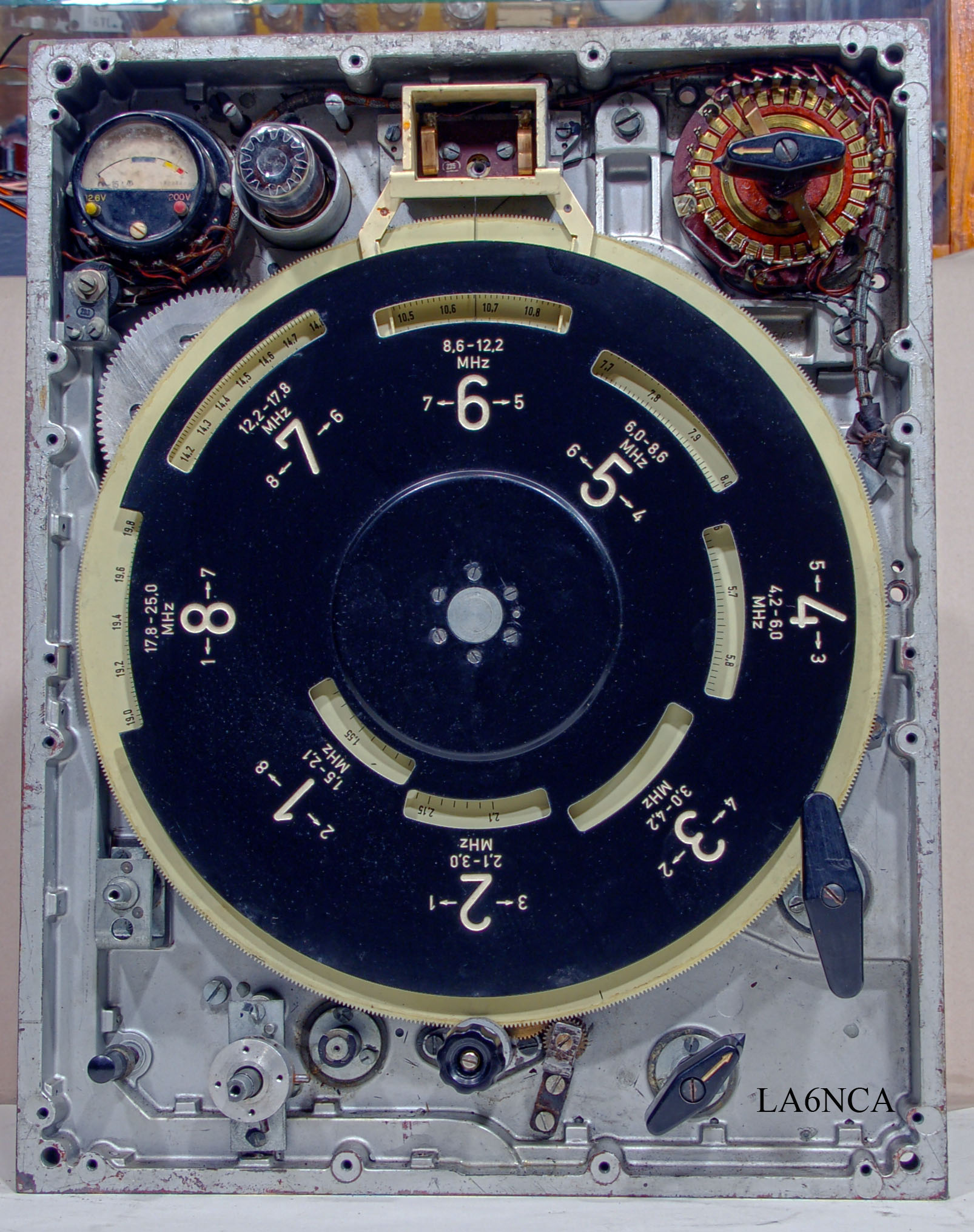
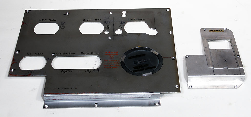
Here is the front plate removed. We see the
round plate showing the 8 frequency
sw8a.jpg
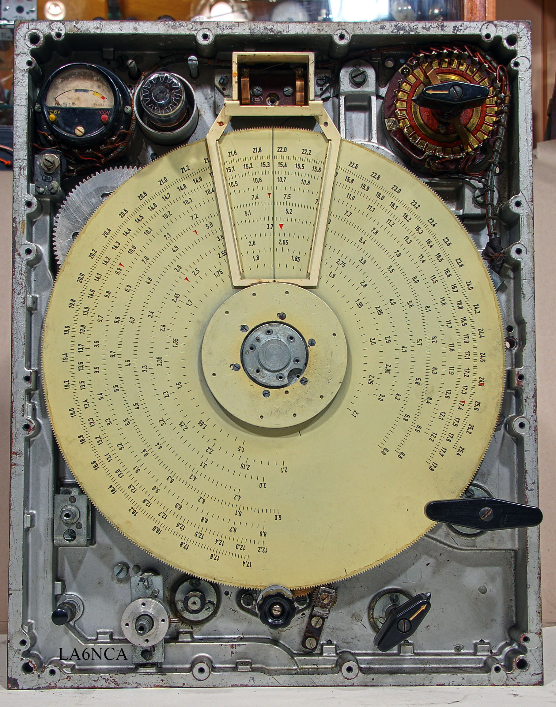
Here's frequency scale plate. All frequencies are typed on this
plate.
Band select disc have small holes that shows the correct
frequency band.

sw3a.jpg
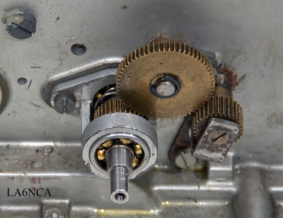
We see here gearwheels for the frequency setting. It is the
big plate showing the frequencies that drives these wheels.
sw4a.jpg
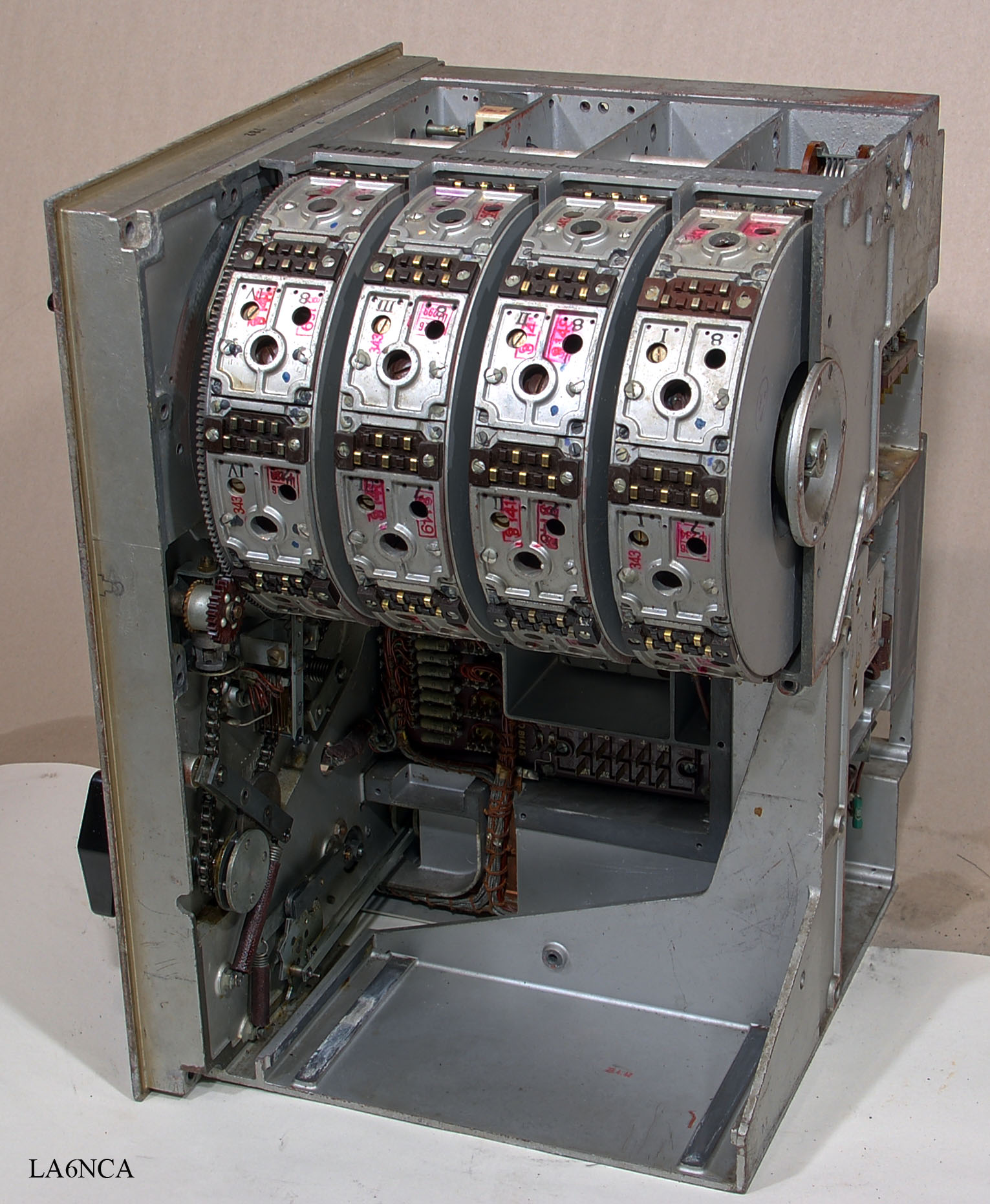
The wonderful fine spool turret with four tuned circuits.
Coil turret has 8 frequency ranges. Wonderful wonderful casting
technique.
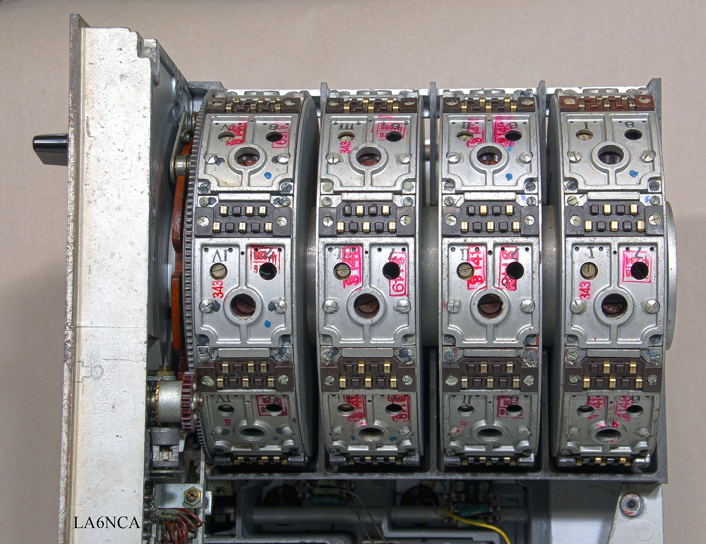
sw6a.jpg
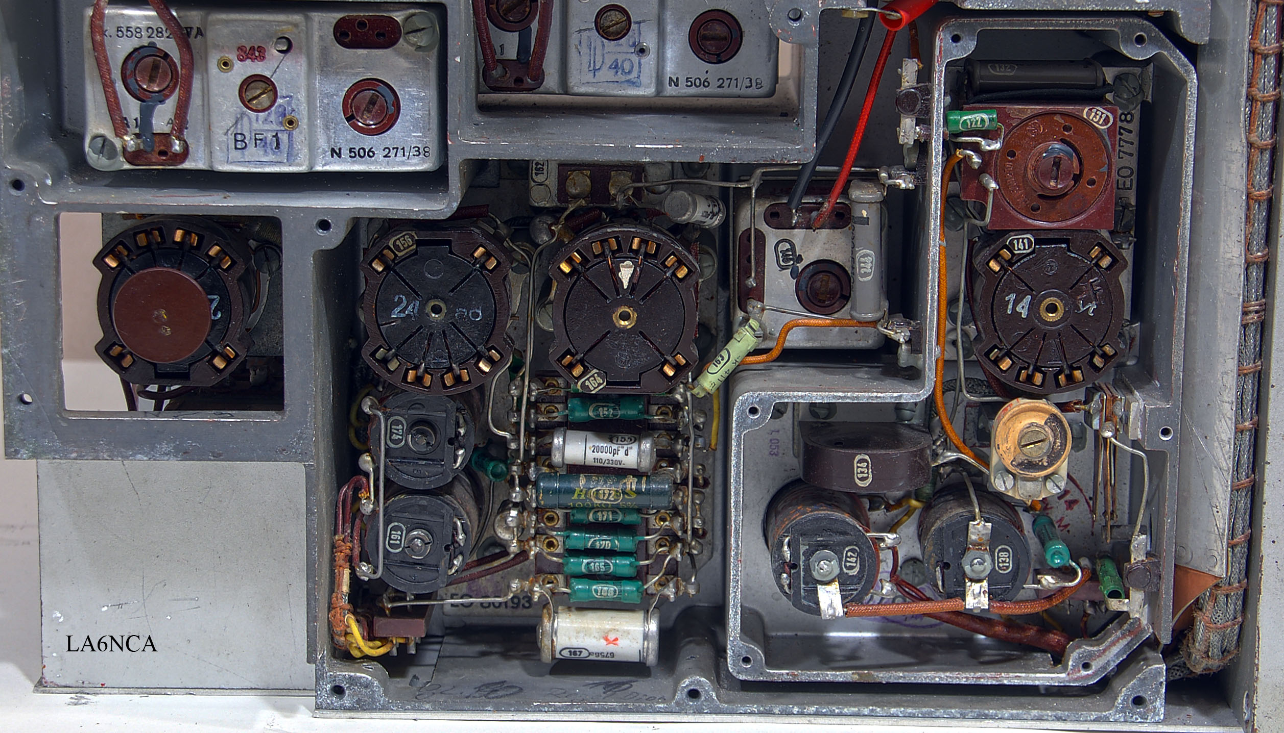
It is very easy to calibrate this radio.
Coils and capacitors can be seen in the small holes.
| This is something very
special. A speed regulator for the coil turret. When selecting the band to listen on this starting to rotate at a constant speed. It stops when it has reached the desired frequency band. Very amazing. |
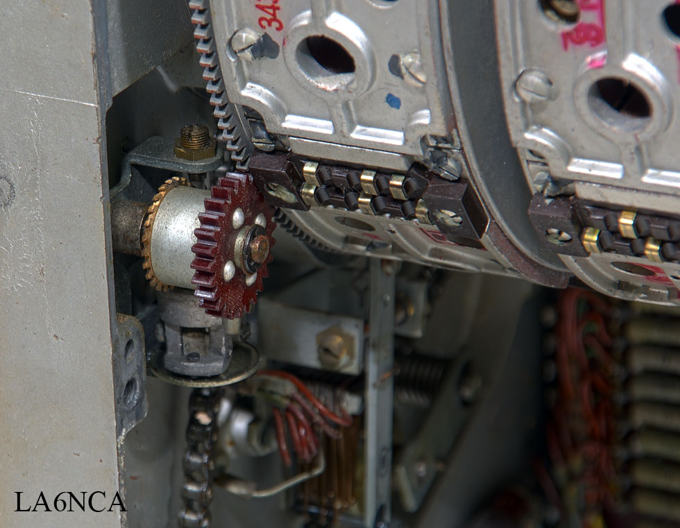
| This is the mechanics of the
frequency setting. These wheels are in engagement with the large plate where frequencies are printed. These sprockets are spring-loaded so that no backlash exists . The first sprocket is divided. Is partially hidden in the picture. |

sw13a.jpg
sw14a.jpg
sw15a.jpg
sw16a.jpg
sw1a.jpg
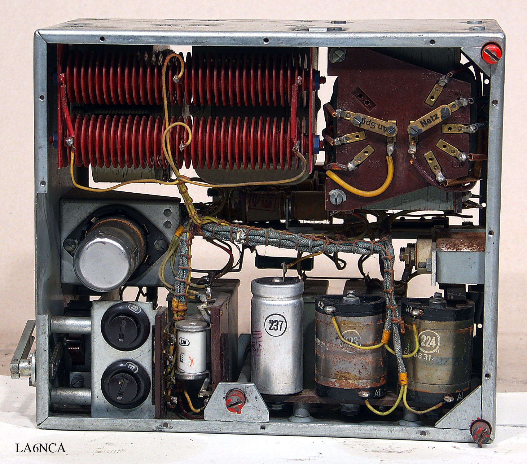
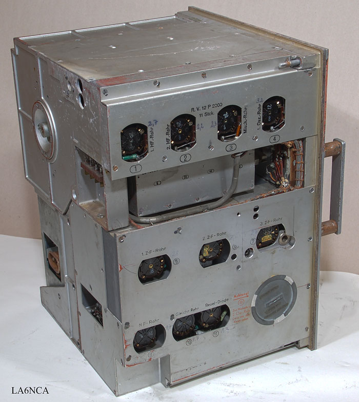
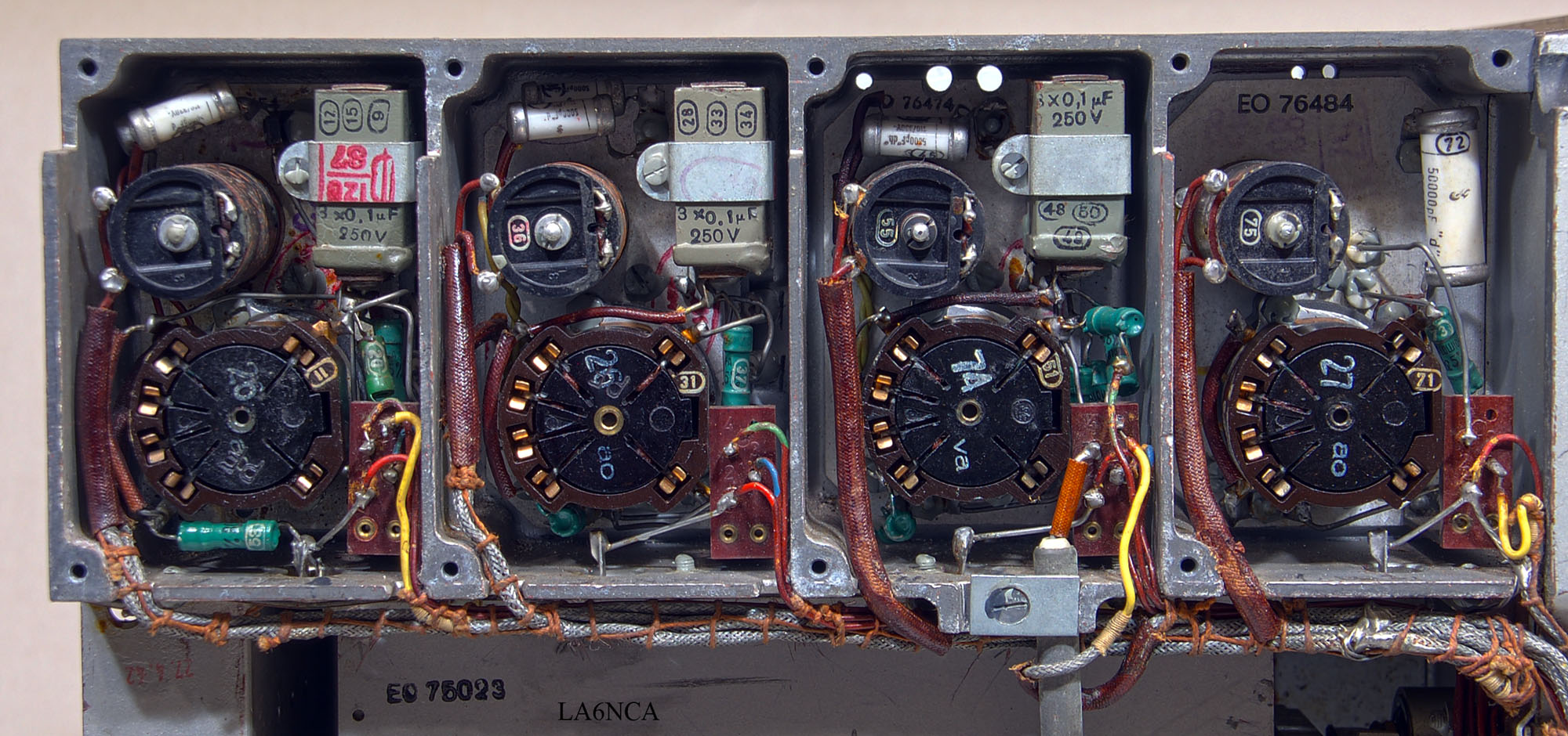
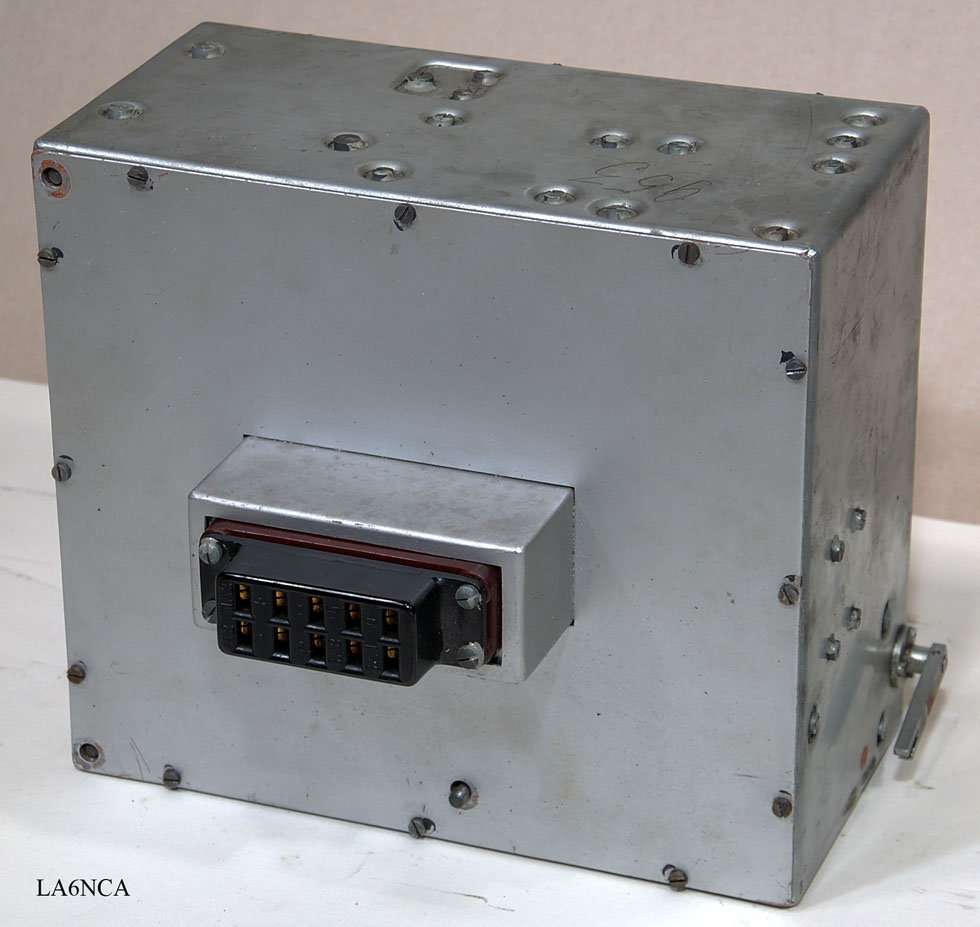
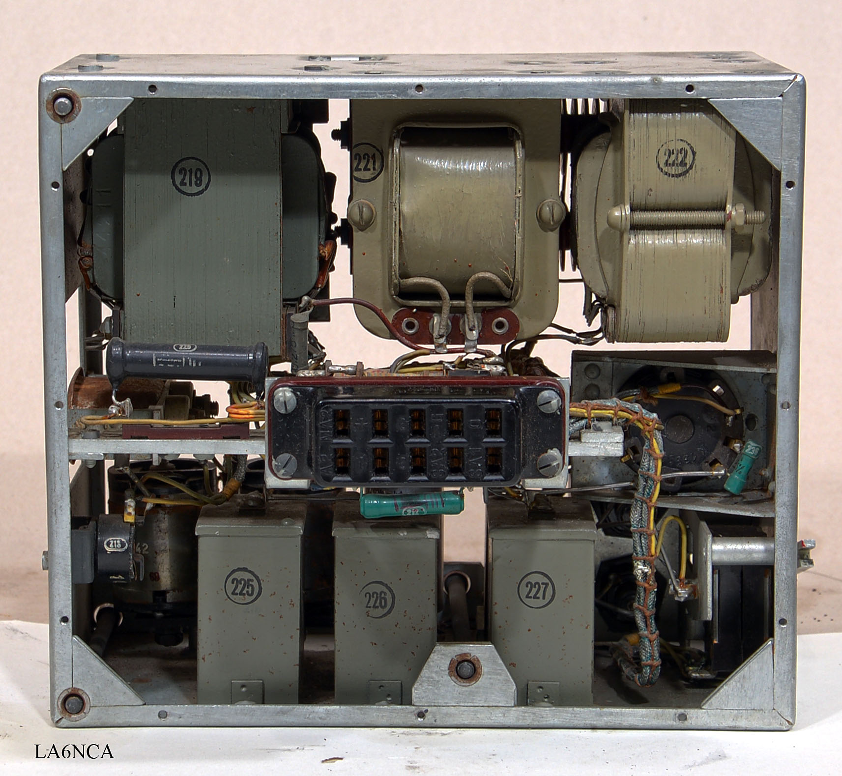
| Power supply. On top we see
the transformer and two chokes. At the bottom are the capacitors. In the middle we see the connector into the actual radio. This is the same type of connector used in Lorenz Fug10 and Fug16. |
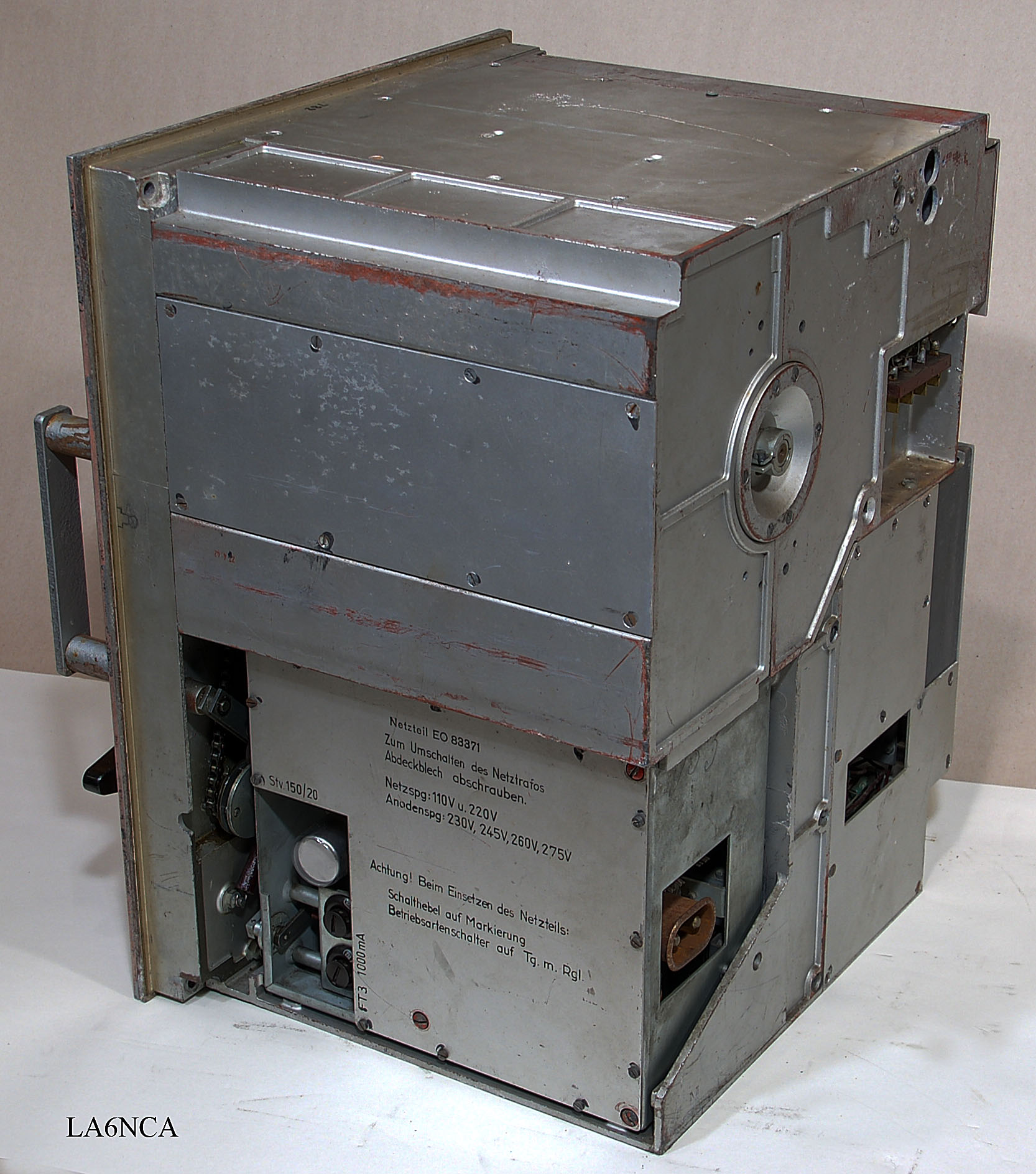
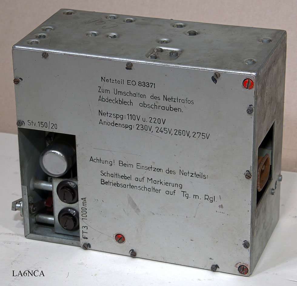
| Here is the front of the
Power. We look at the top rectifier and mains voltage selector Bottom we have the voltage regulator tubes, fuses and mains filter. ,. |
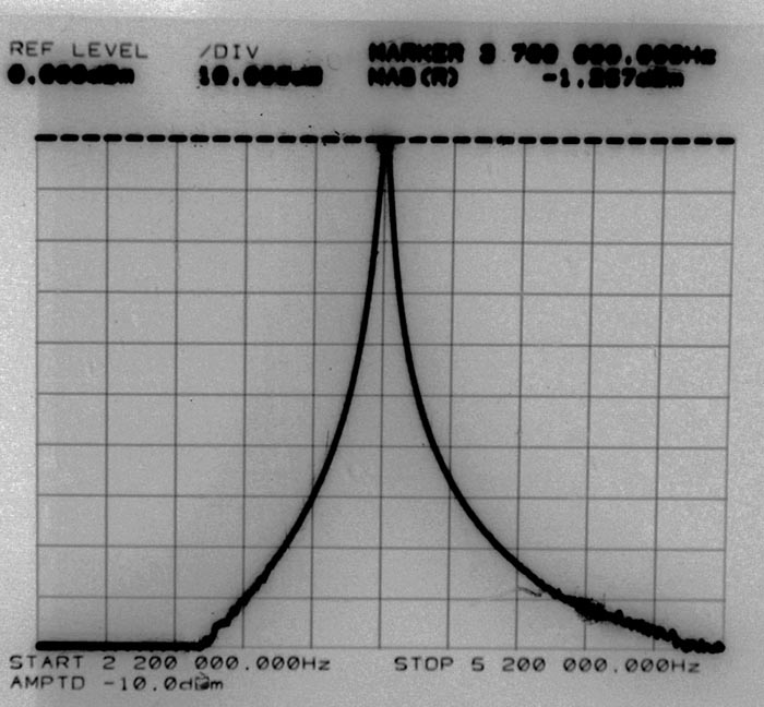
| This is the frequency
response curve of the three stages RF filter and
amplifier. Center frequency is 3700 kHz The signal inn is coupled to antenna input connector. The signal ut is taken from the mixer tube grid. It is 100 dB vertically in the figure. Horizontally, 300 kHz on each route. Mirror frequency is far below -100 dB down. |
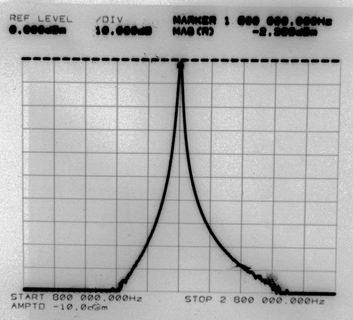
| Here is the center frequency
1800 kHz Horizontally it is 200 kHz on each route. Vertically it is 100 dB. |
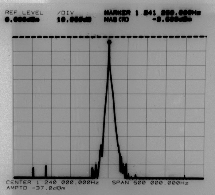
| Here is the curve for MF
filter. The center frequency is 1241 kHz. The filter is set to minimum bandwidth. |