 |
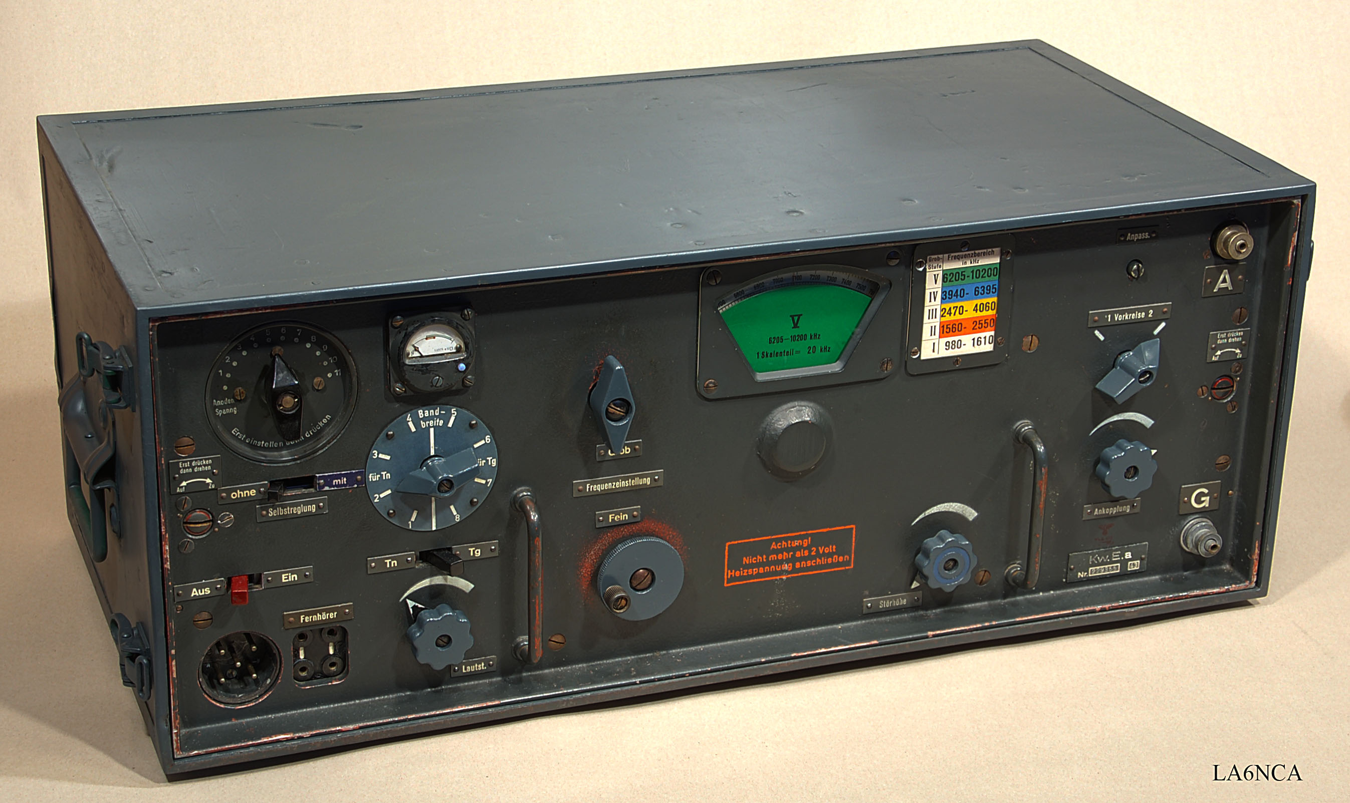
LA6NCA RADIO PAGE Restoration of radio receiver KwEa |
 |
|
LA6NCA RADIO PAGE Restoration of radio receiver KwEa |
|
| On this page I show
restoration work by an KwEa. Having heard much praise of how great KwEa is. Know several telegraph operators who used this in the 50s and 60s. After I was finished with the restoration, I understand now that this is one of the best CW receivers made. This radio is very difficult and advanced to work with. I spent over 150 hours on restoration, power and audio amplifier. |
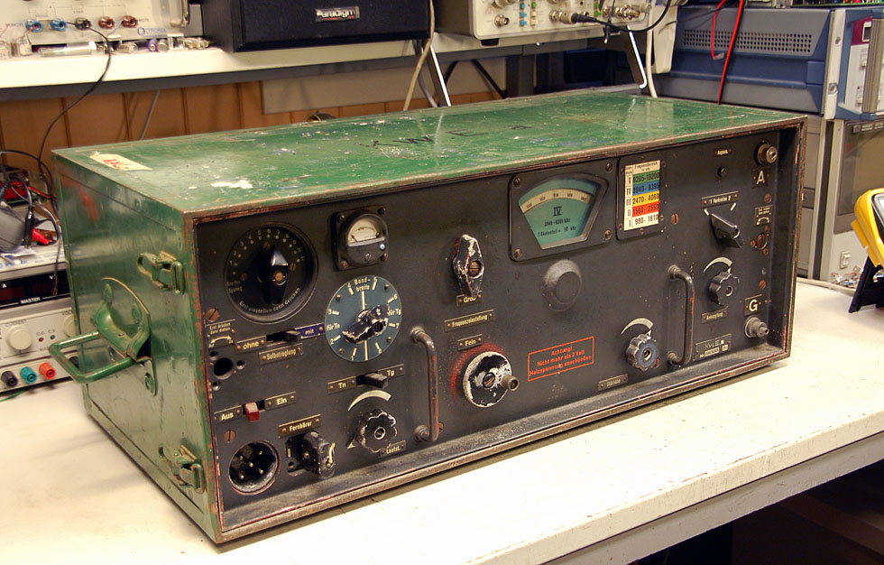
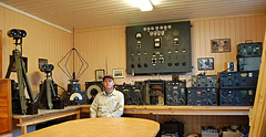
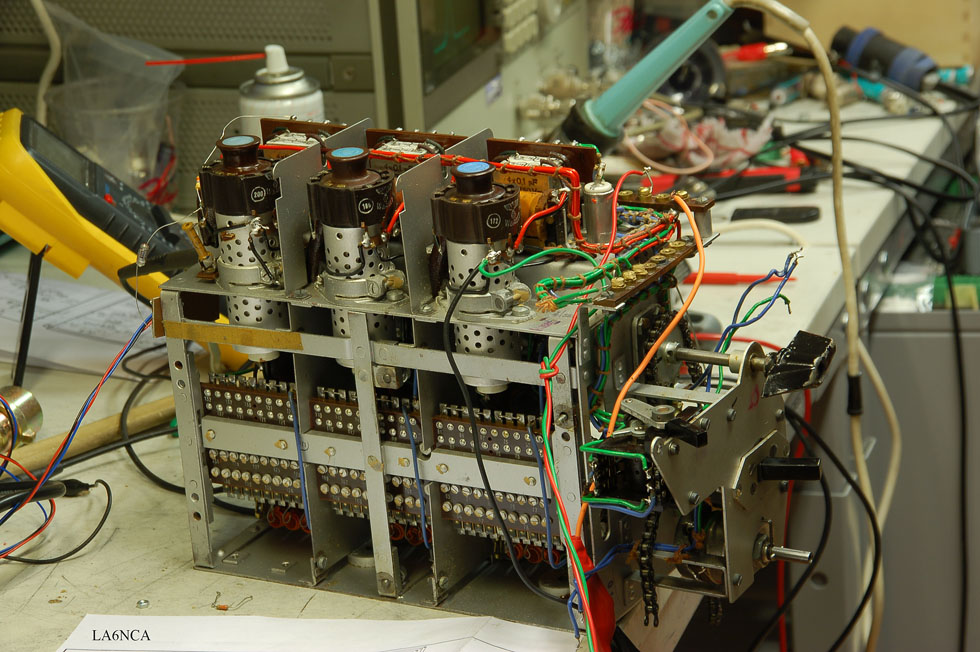
I have now placed the receiver on the lab bench.
The radio is here ready for test.
It works, but is unstable and not quite optimal.
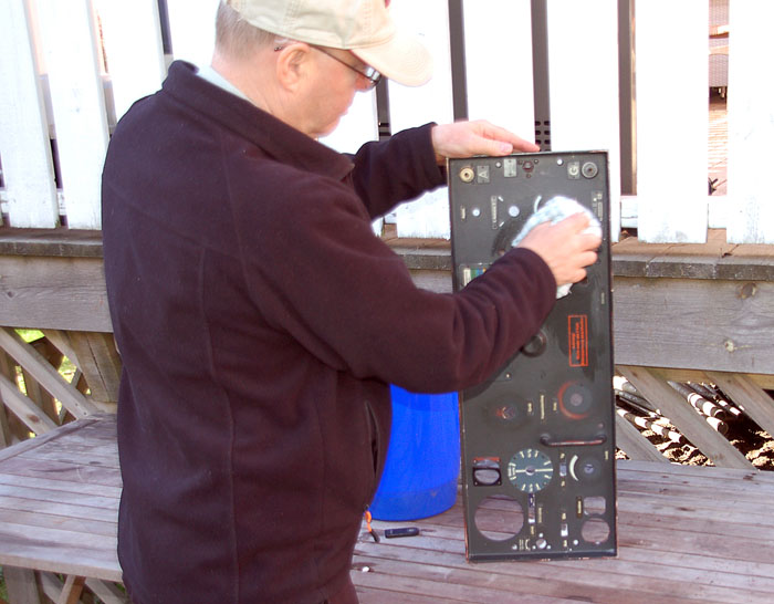
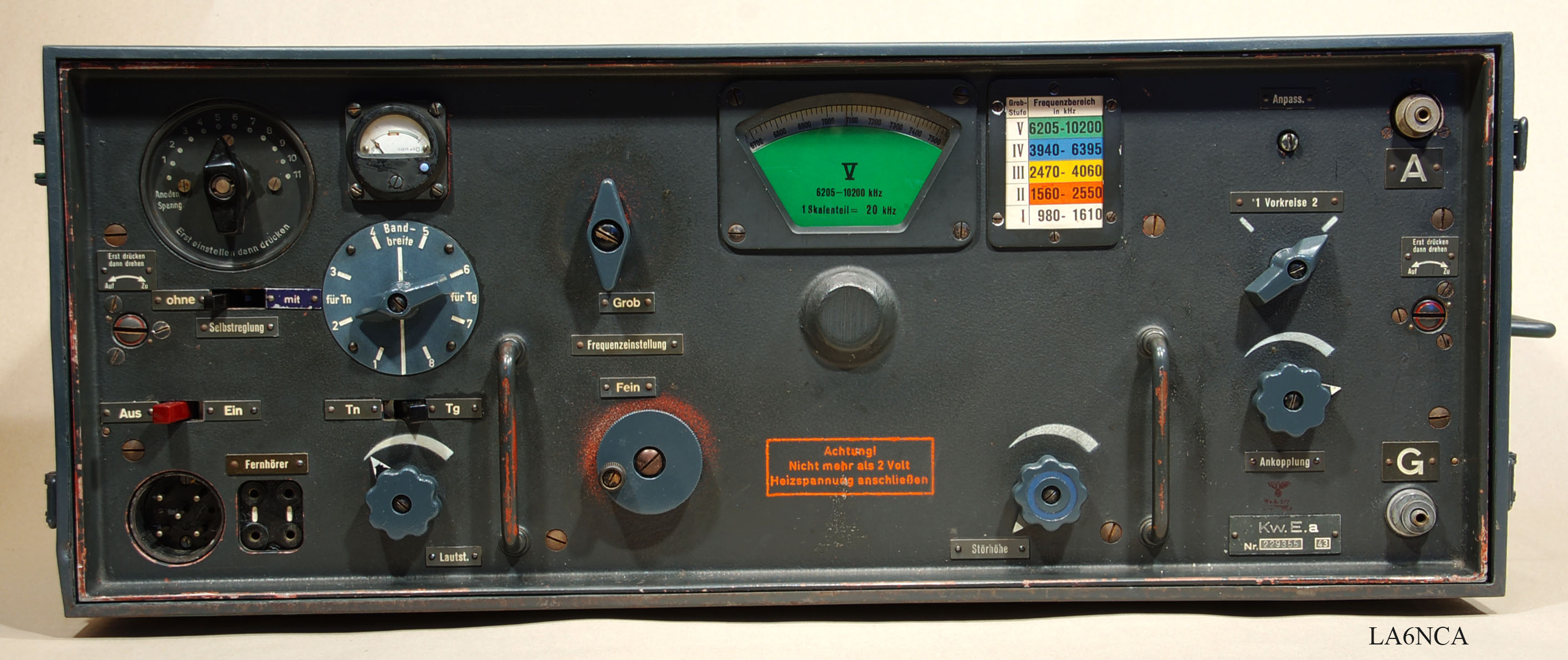
Front plate is removed and washed with soap and water.
TUBE TEST
The first thing I do is test all the tubes.
Three were weak and needed to be replaced.
I using a tube tester built by LA8AK.
CAPASITOR TEST
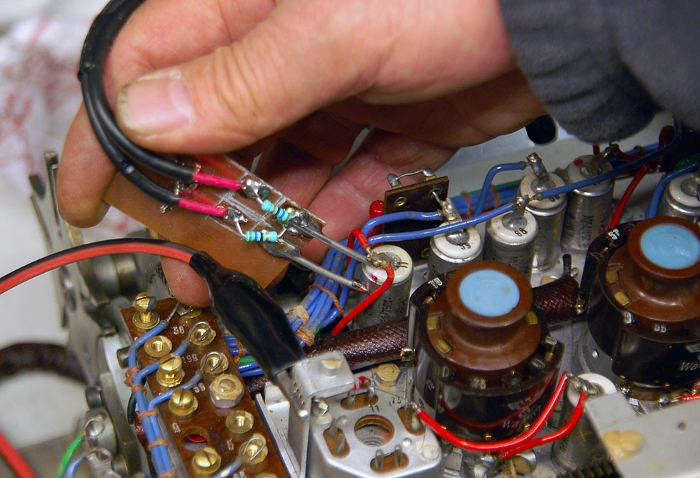
| The next thing I do is test
all the decupling capacitors. I have created a probe that makes it unnecessary to solder out the capacitors for test. I use a network analyzer to measure the frequency response of the capacitor. My probe has two pins. One is GND. The other is connected to the signal from the analyzer via an 56 ohm resistor. The signal is transmitted to the input of the analyzer from the same pin via a 56 ohm resistor. In this way, I can measure the reactance in the capacitor wiry accurate. The rest of the circuit connected to the capacitor influencing little on the measurement result. A signal generator and oscilloscope can be used instead for an analyzer. Frequencies from 1 MHz to 10 MHz should be used. |
TUBE CORROSION PROBLEM
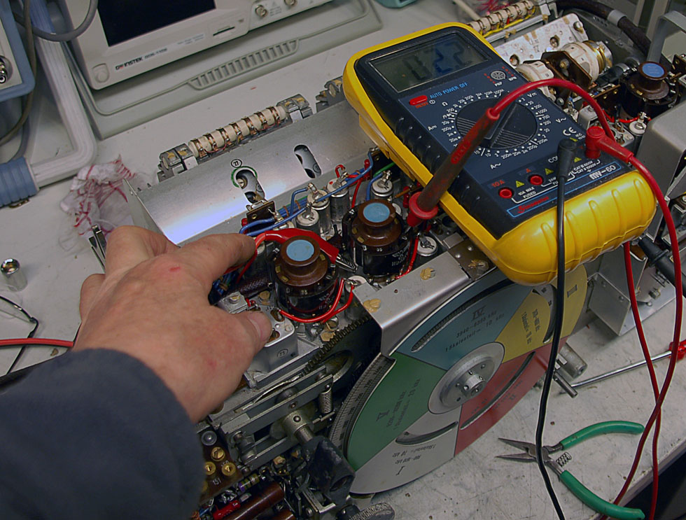
| One problem I often see in
German WW2 radios is that connection from tube sockets to
GND is bad. There may be corrosion in the tube base and screws. To find such problems, I use the following method: I add a DC current of one ampere to the tube base. Then I measure with an mV meter the voltage between tube socket’s and GND. Here I measure 2.2mV. That is 2.2 mOhm. It's good. In one of tube socket’s I measured 100 mOhm. This is wrong and had to be fixed. |
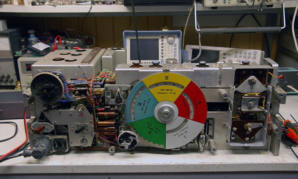
RF SECTION CALIBRATION
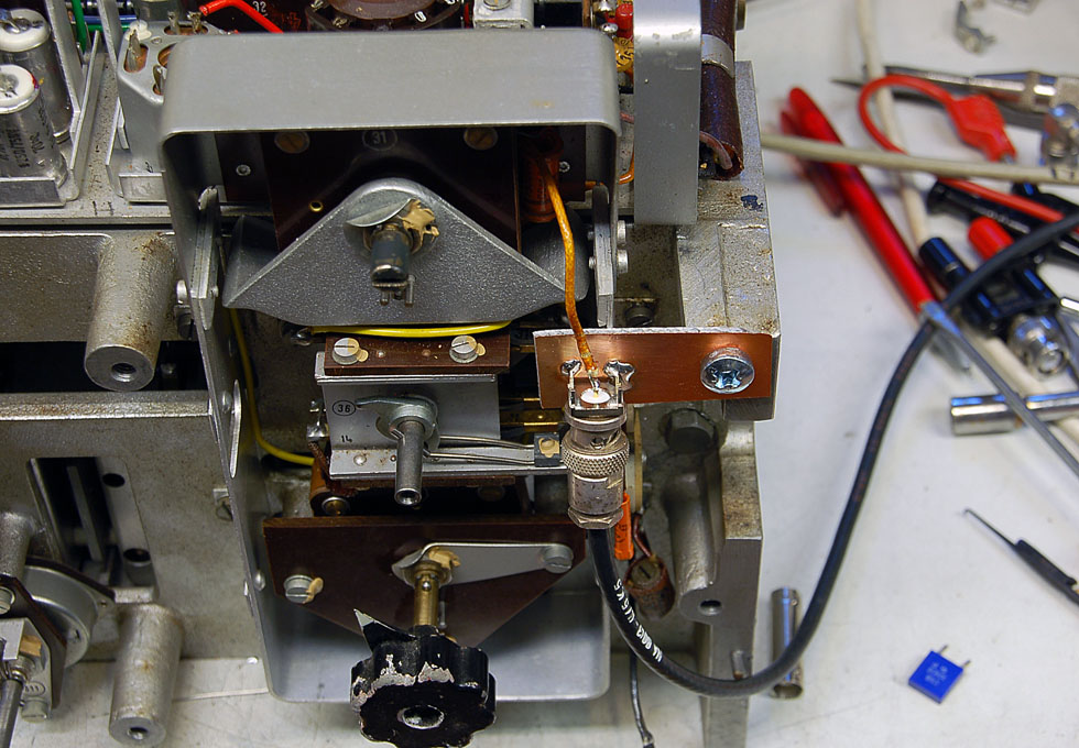
Have here mounted a temporary BNC antenna input.
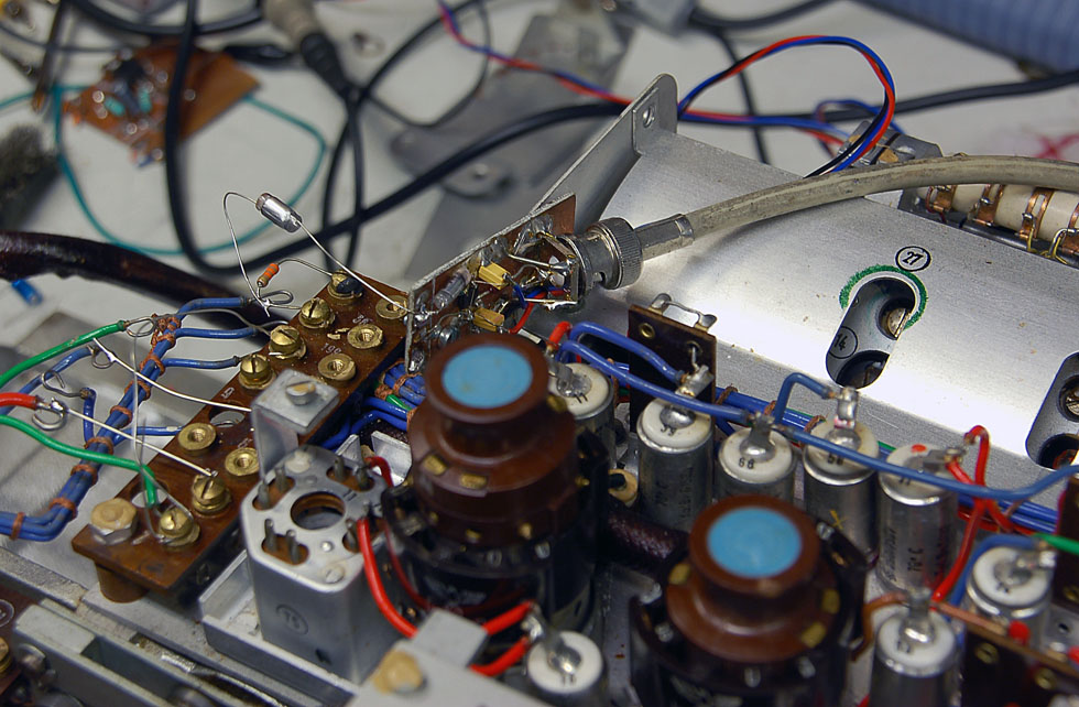
Here is my HF probe with amplifier mounted on the HF section.
I can now measure the frequency response in the HF section.
Using this setup when I calibrate HF circuits.
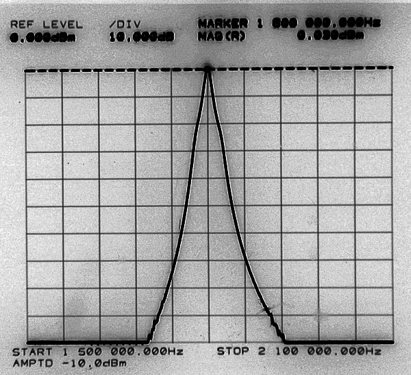
| Frequency response of HF
section at 1.8MHZ. X = 60 kHz, Y = 10dB Very good curve. From top to bottom of the curve is the incredible 100dB The mirror frequency attenuation will be very good. |
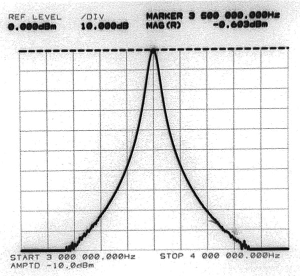
Frequency response of HF section at 3.5 MHz.
X = 100 kHz, Y = 10dB
The frequency response of the HF section at 7 MHz.
X = 200 kHz, Y = 10dB
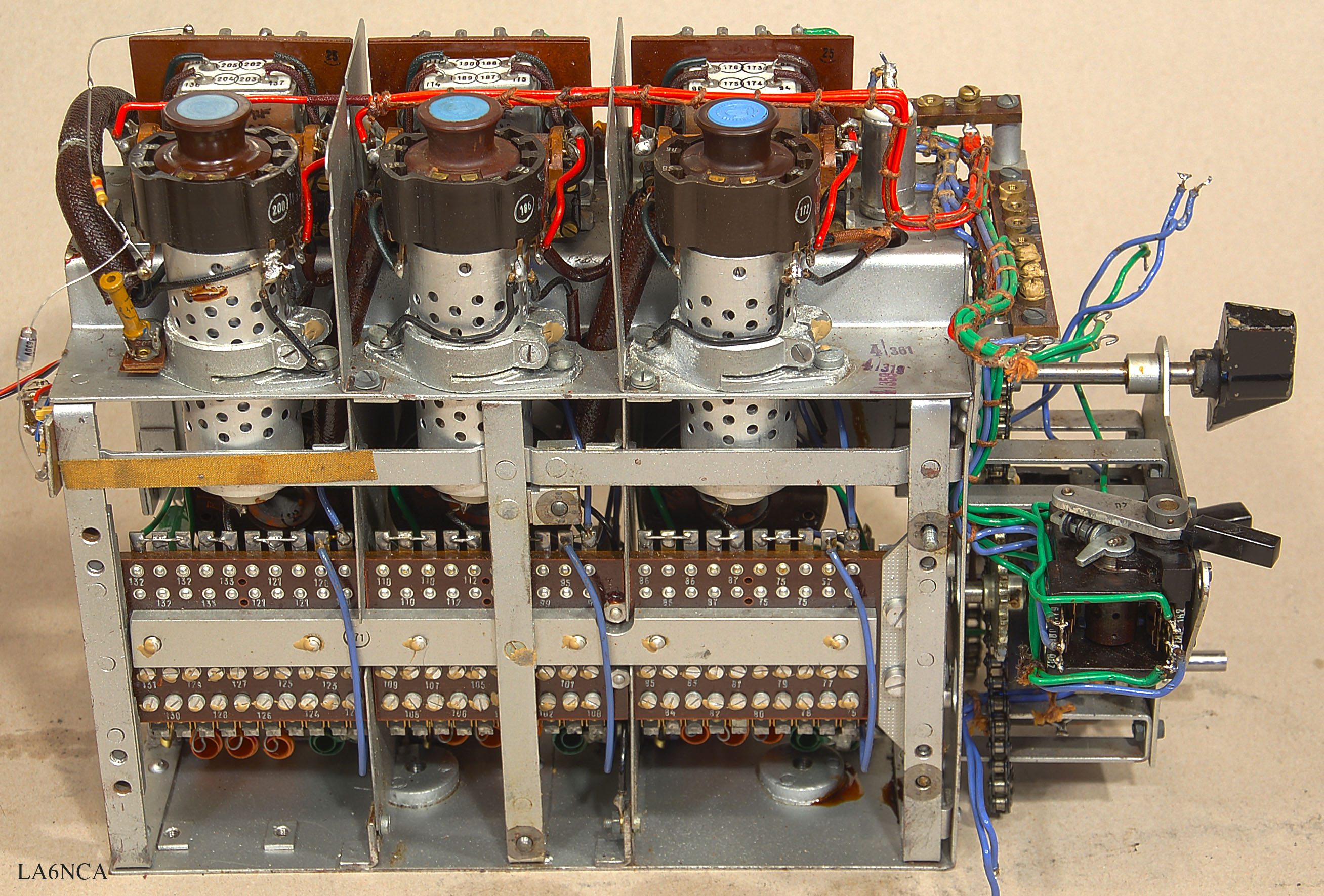
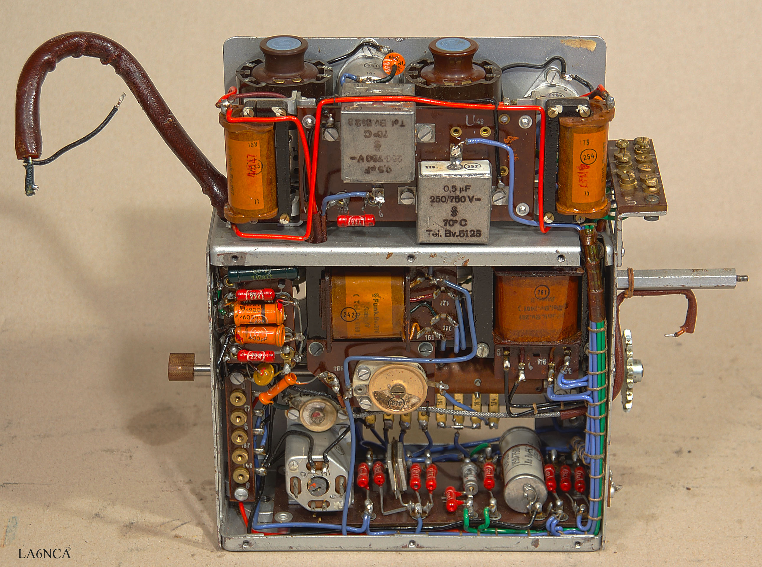
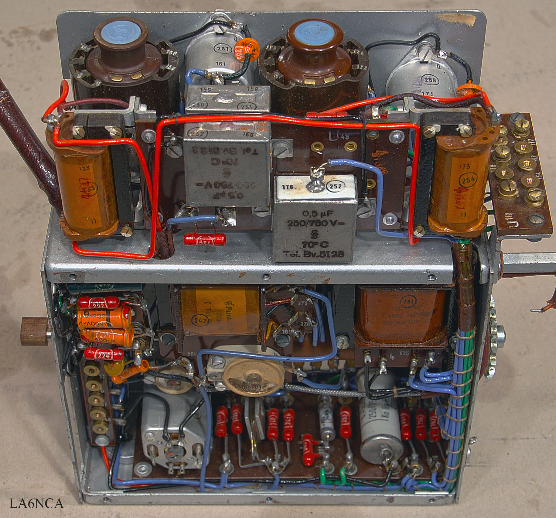
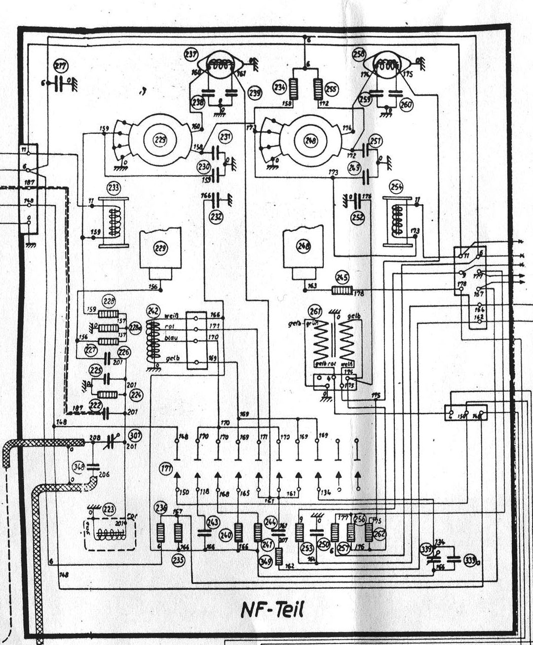
MF SECTION CALIBRATION
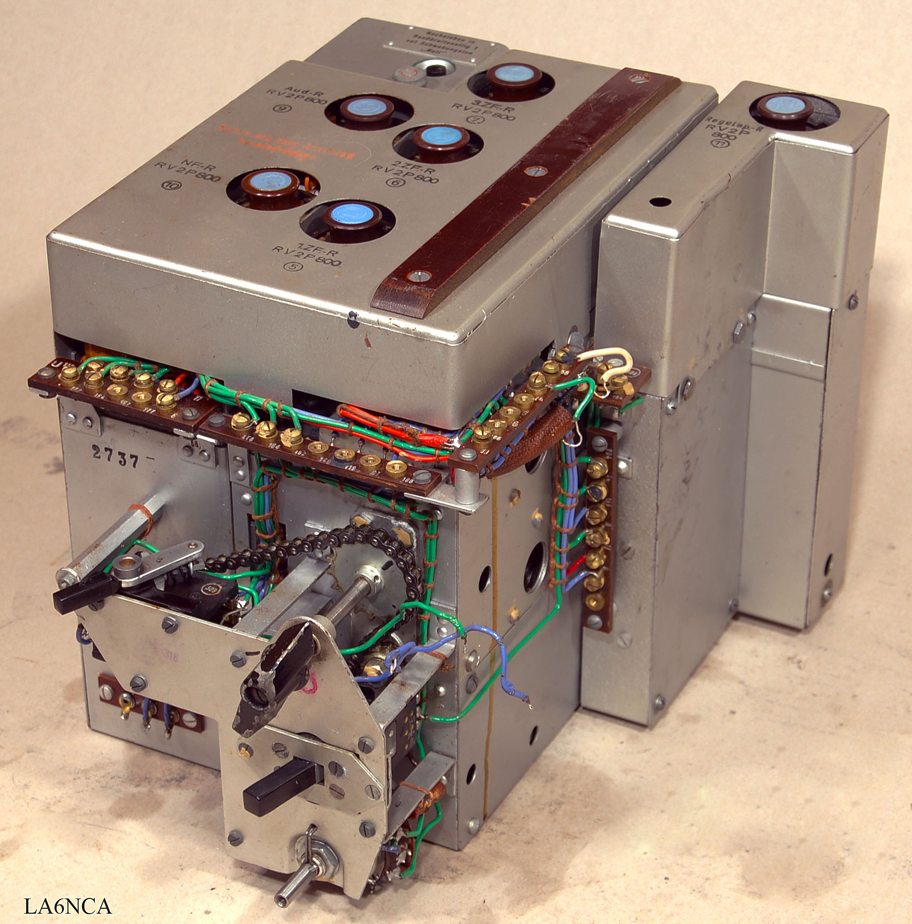
kwea21a.jpg
MF amplifier, audio amplifier, oscillator and regulator.
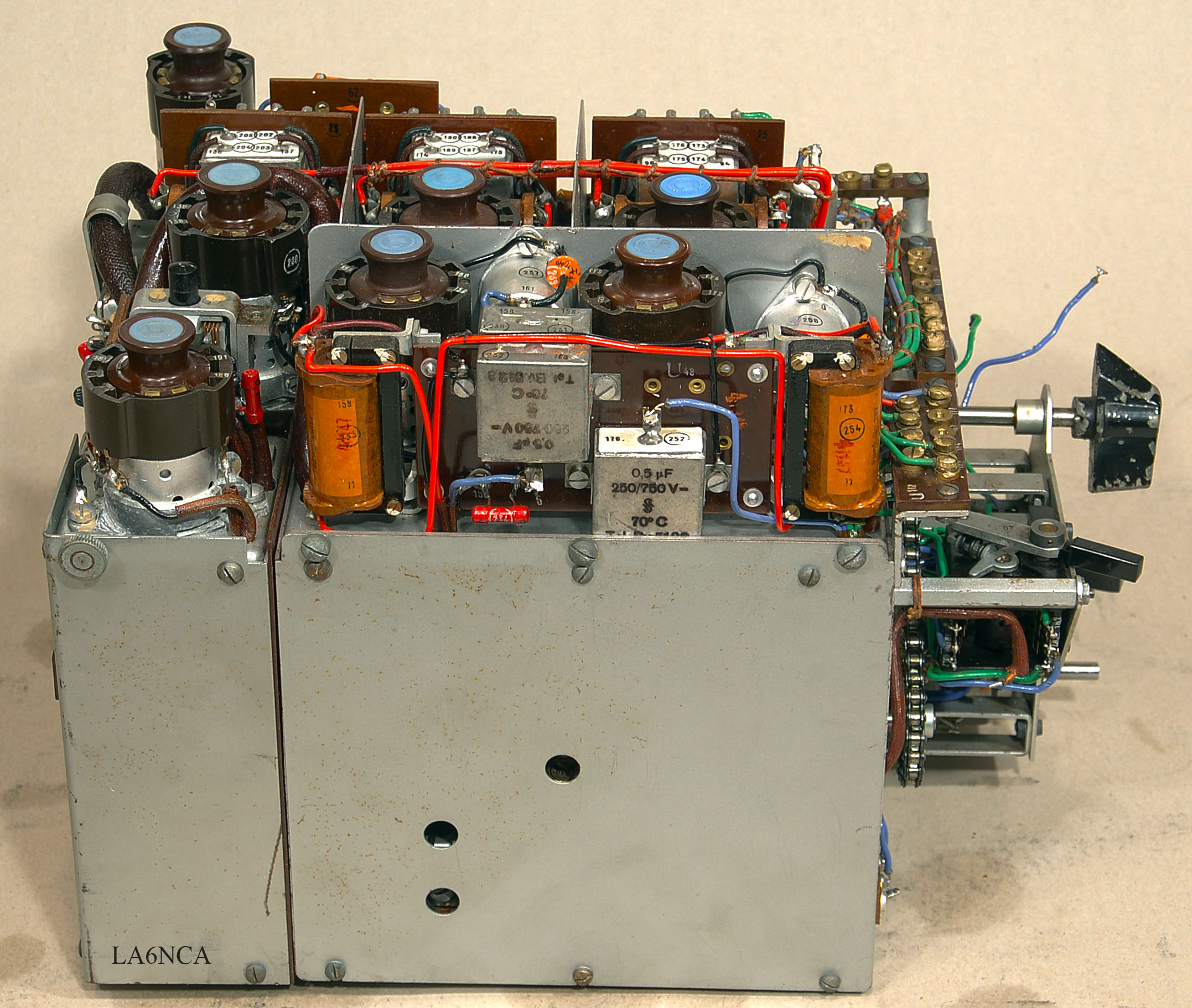
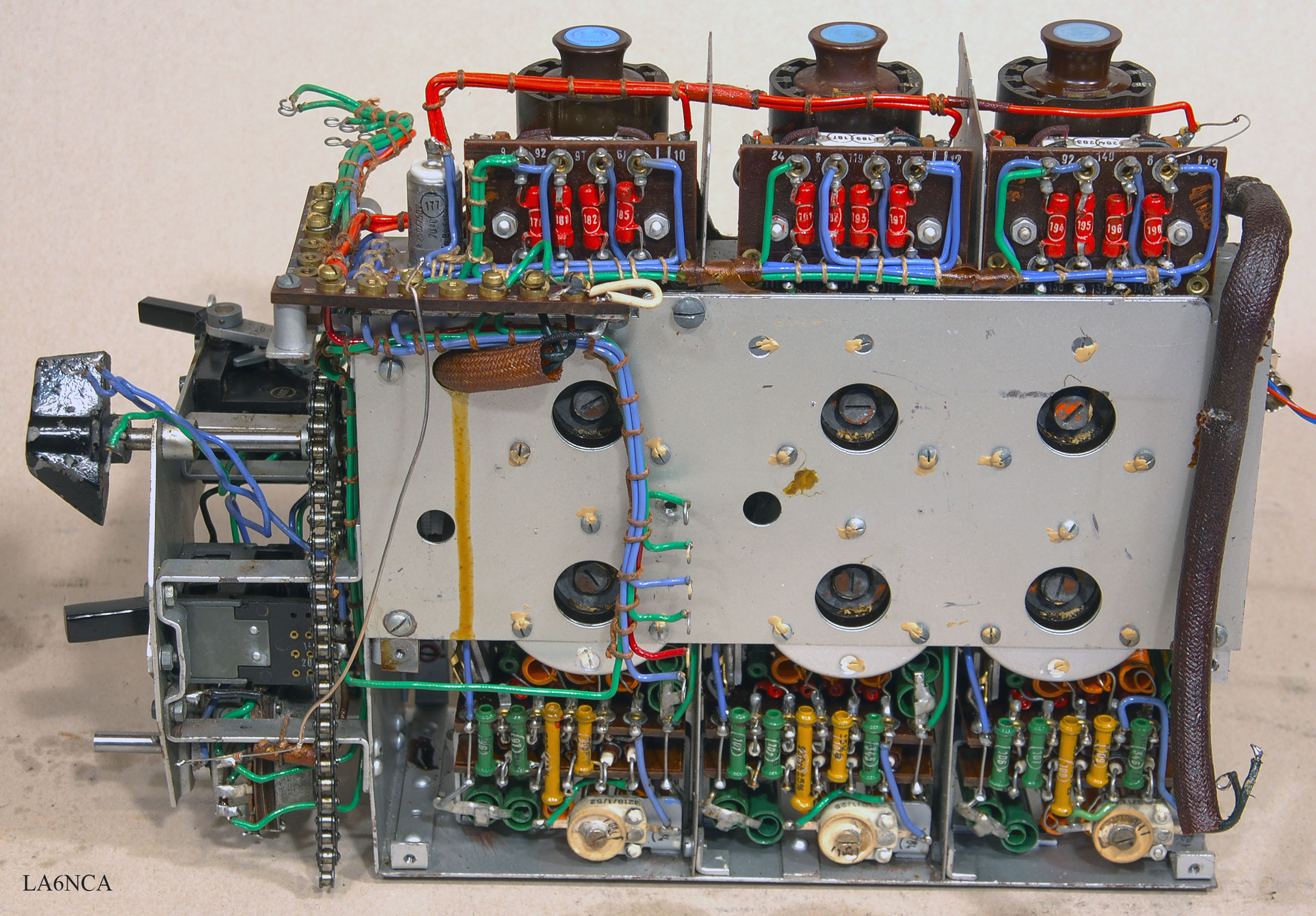
kwea22a.jpg
Viewed from the left side without cover.
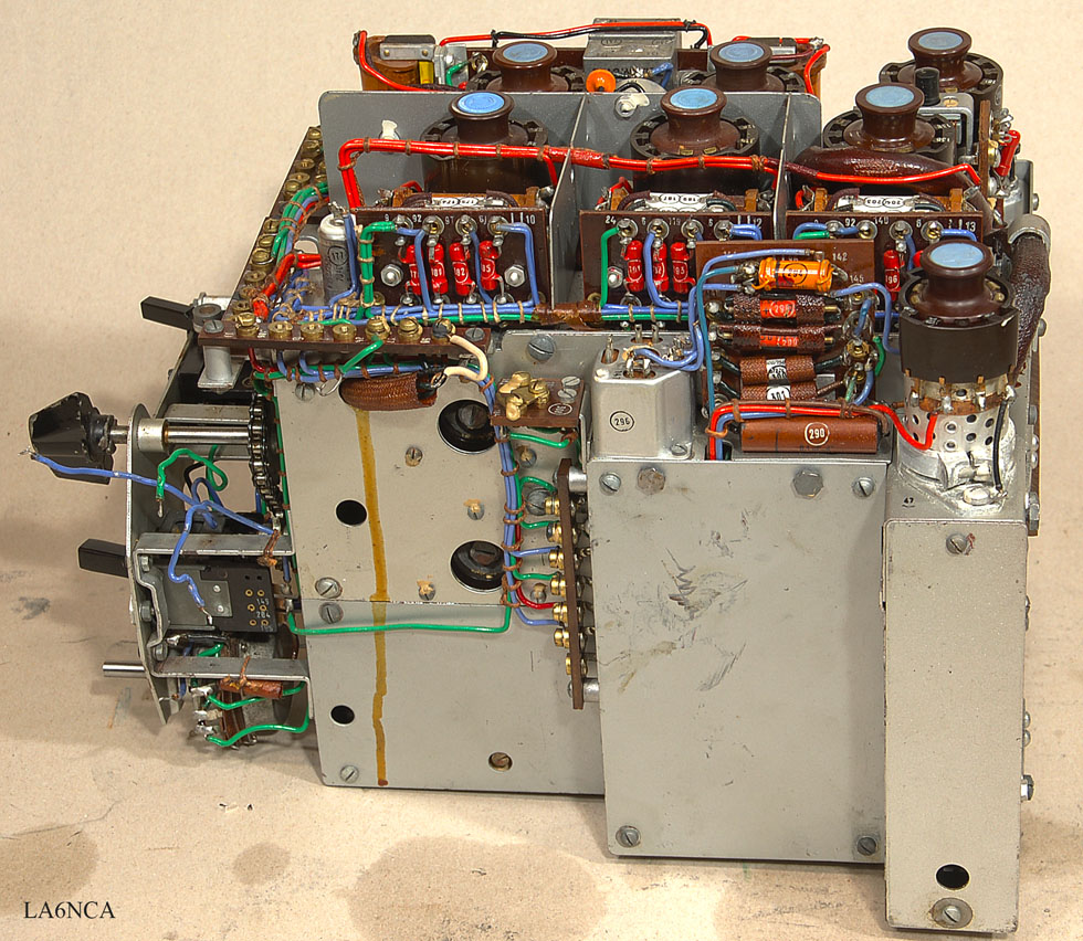
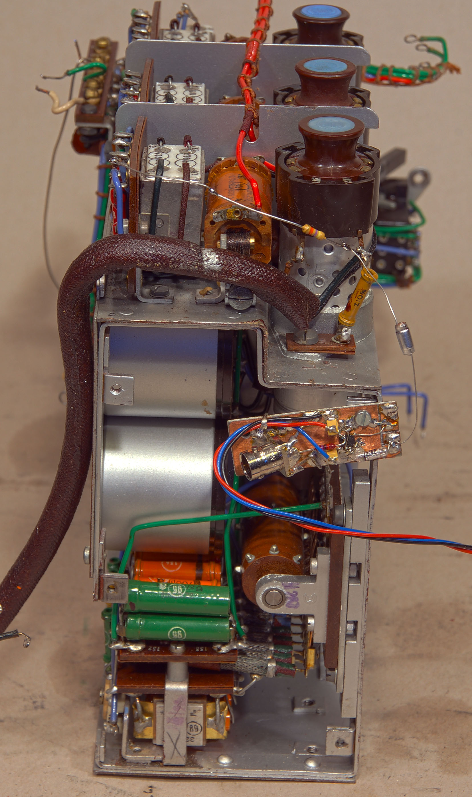
kwea23a.jpg
Viewed from the right side without cover.
kwea27a.jpg
Have here removed MF amplifier with filter.
Am very impressed with this.
kwea28a.jpg
MF amplifier viewed from the other side.
We see here the large coils in the filter.
kwea29a.jpg
MF amplifier with my HF probe mounted.
I am going to measure and calibrate the MF filter.
MF amplifier on the lab bench.
Network analyzer can be seen in the background.
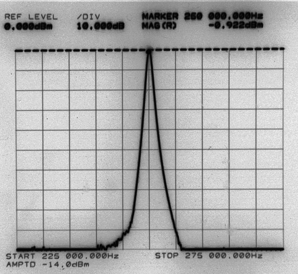
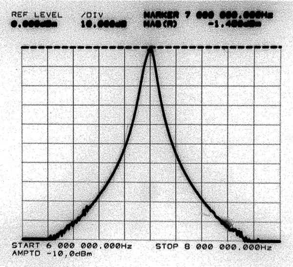
| I have here trimmed MF
stage. The frequency response was amazing. I have never seen such a MF curve before. !!! This must be one of the best HF receivers made??. The resolution is 5 kHz and 10 dB. The bandwidth at -60 dB is 10 kHz At -90 dB bandwidth is 17 kHz. Bandwidth 5, 6, 7 and 8 |
Bandwidth 4
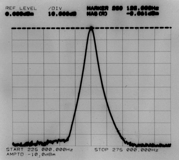
Bandwidth 3
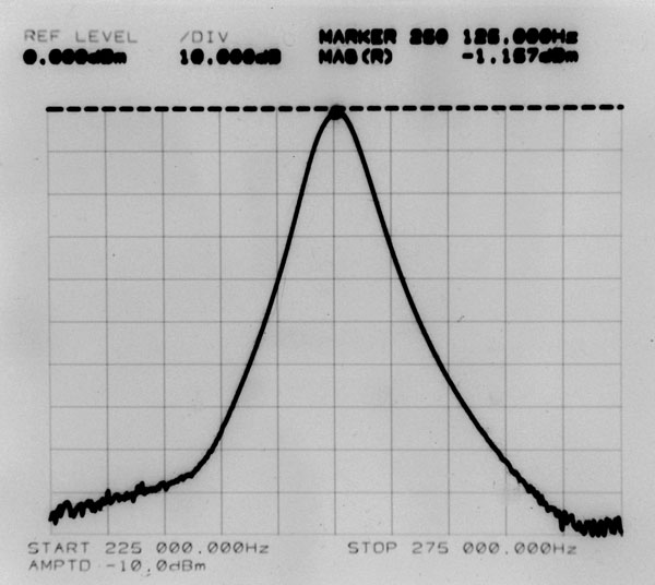
Bandwidth 2
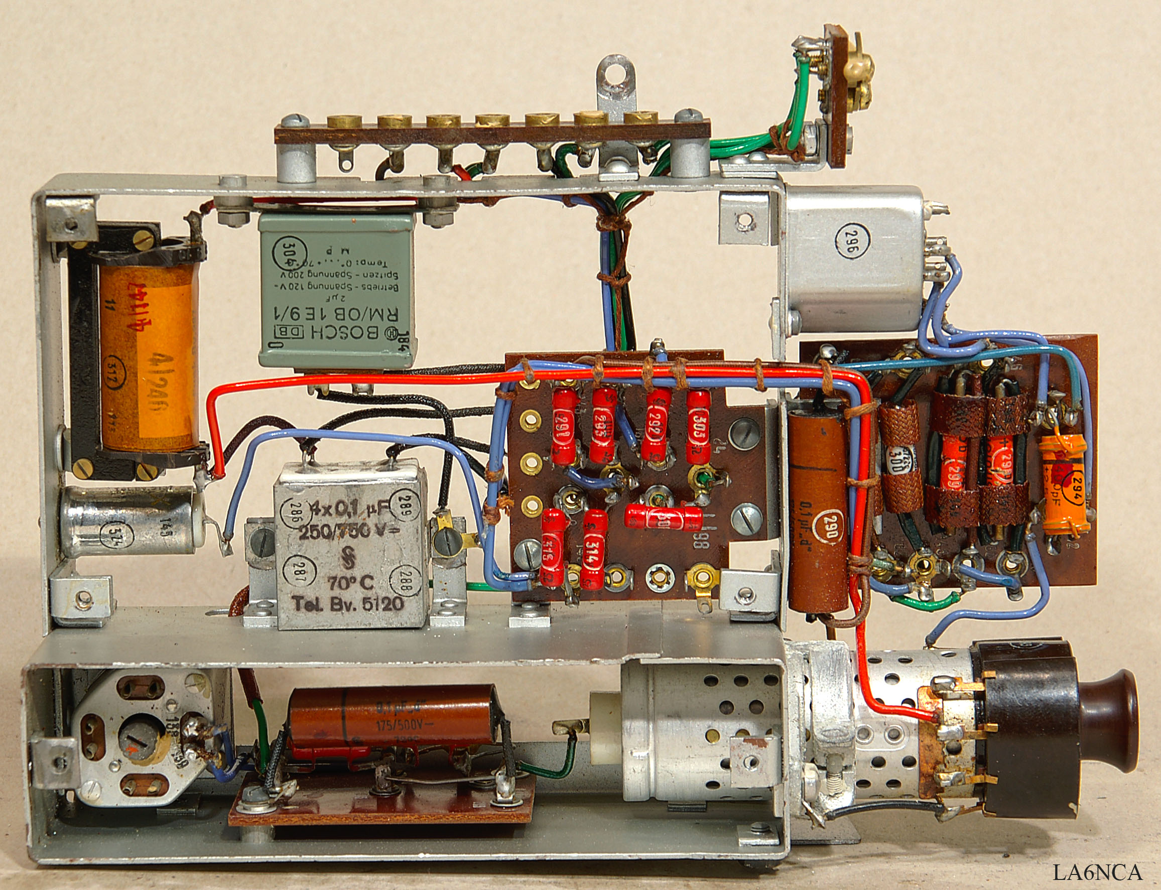
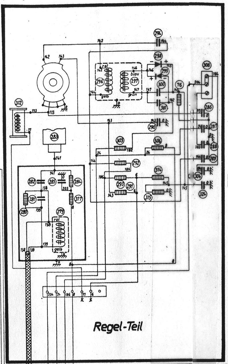
RF GAIN REGULATOR SECTION
kwea42a.jpg
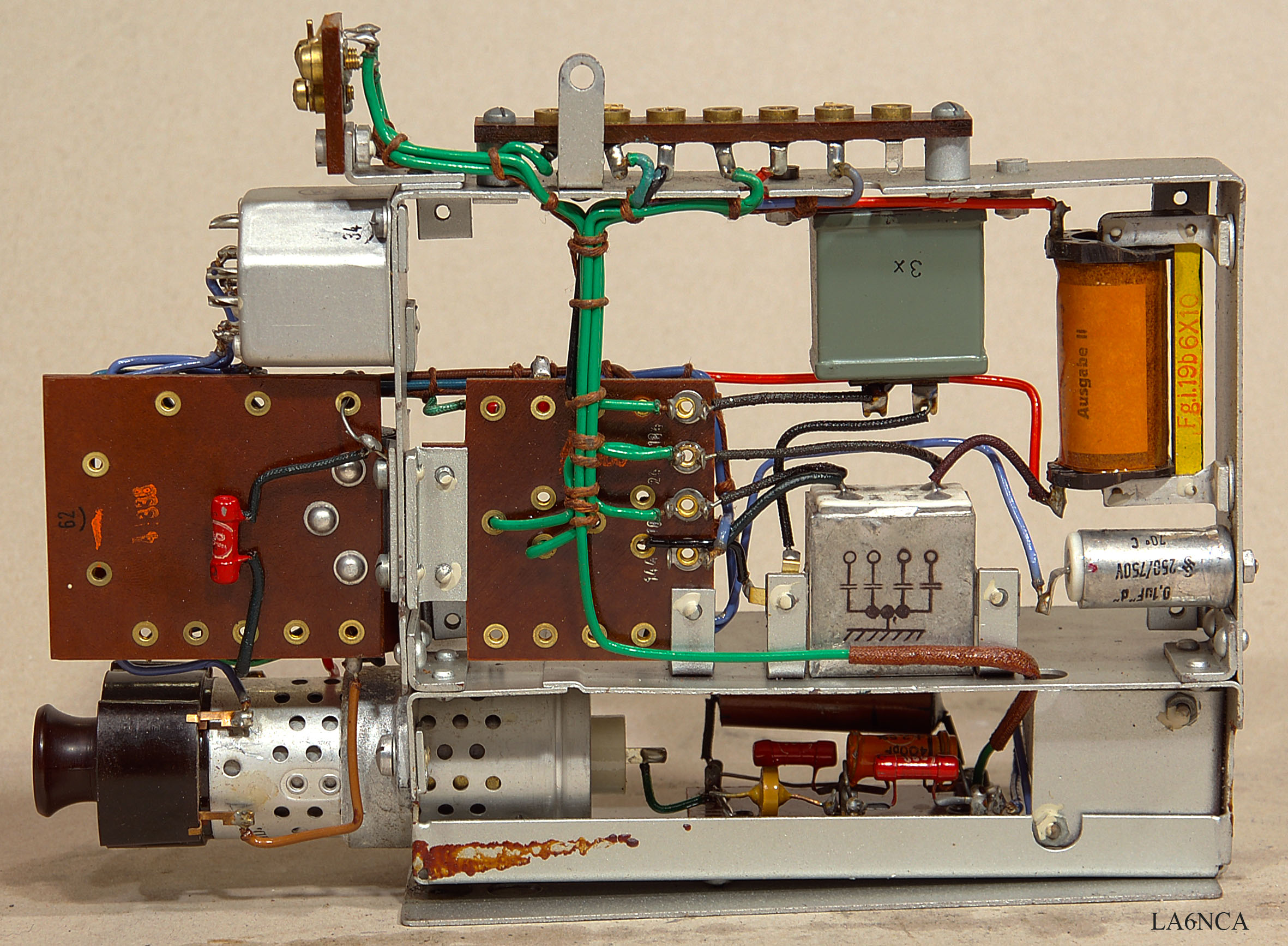
kwea43a.jpg
kwea41a.jpg
| Input signal to the
controller's is the output signal from MF amplifier. This also goes to the LF amplifier. When MF signal increases, RF amplifier reduce gain. Net 24 is the gain control signal to RF section. |
AUDIO SECTION
kwea17a.jpg
Audio amplifier with audio filter.
kwea18a.jpg
kwea40a.jpg
Frekvensresponce audio amplifier for AM reception.
Audio amplifier frekvensresponce for wide CW reception.
Audio amplifier frekvensresponce for narrow CW reception.
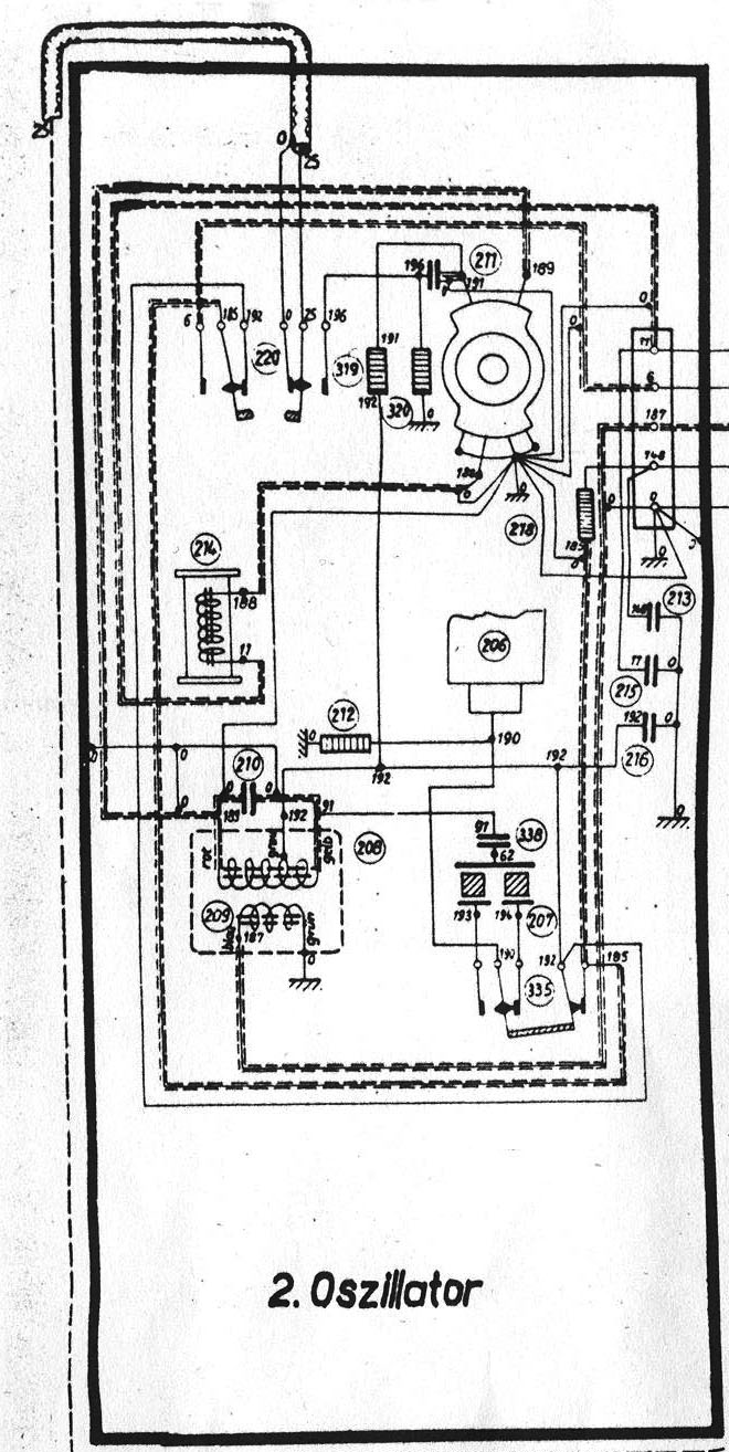
OSCILLATOR SECTION
kwea19a.jpg
| The oscillator used for CW
and SSB reception. It contains two crystals. Upper and lower sidebands. |
The crystal is very sensitive to
mechanical impact.
Handle with care.
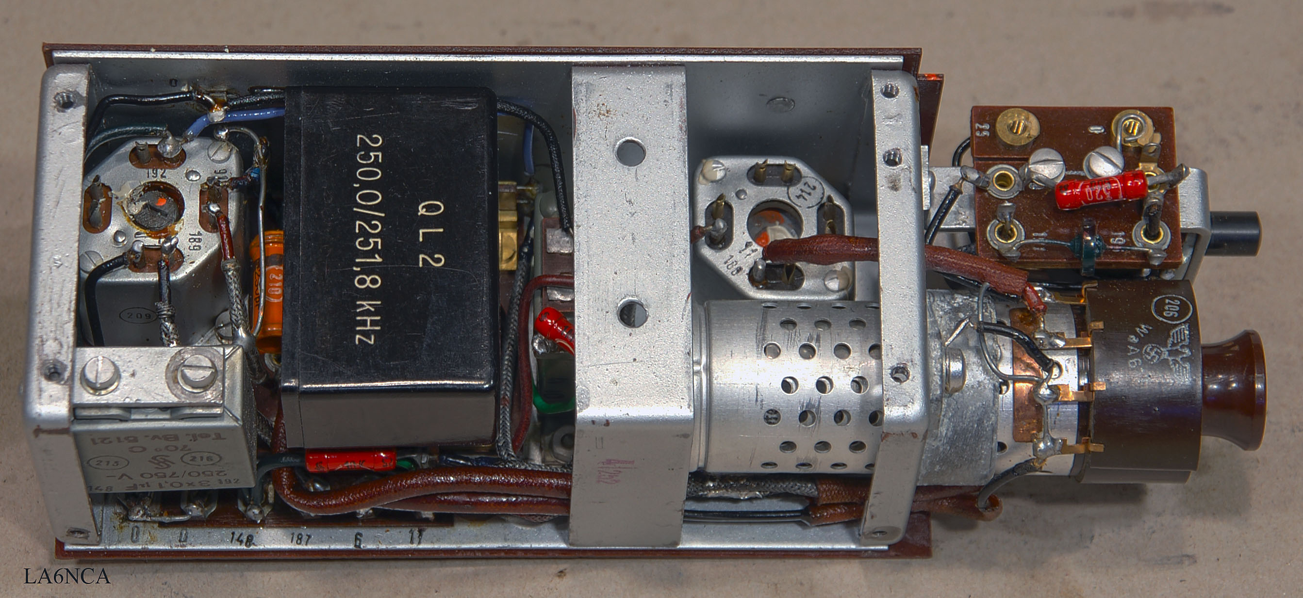
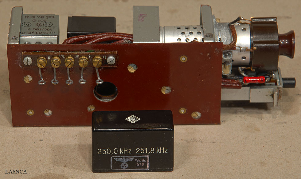
kwea39a.jpg
| This is the BFO and the
calibration oscillator. A crystal of 250 kHz is used. Intermediate Frequency of KwEa is 250.900 KHz. This gives a CW tone of 900 Hz. Overtones from the same crystal are used for calibrating. This crystal is used in MF position 1-8. This results in LSB reception. A crystal of 251.800 kHz is used in MF position 9 This gives USB reception. |
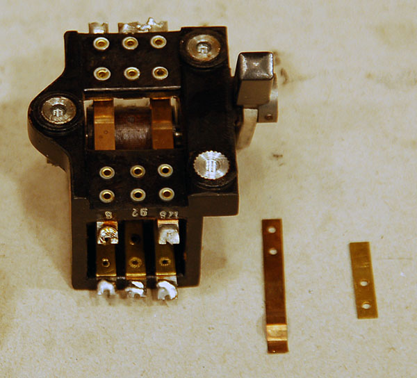
Several switches were broken and had to be repaired.
The parts I found inside the radio.
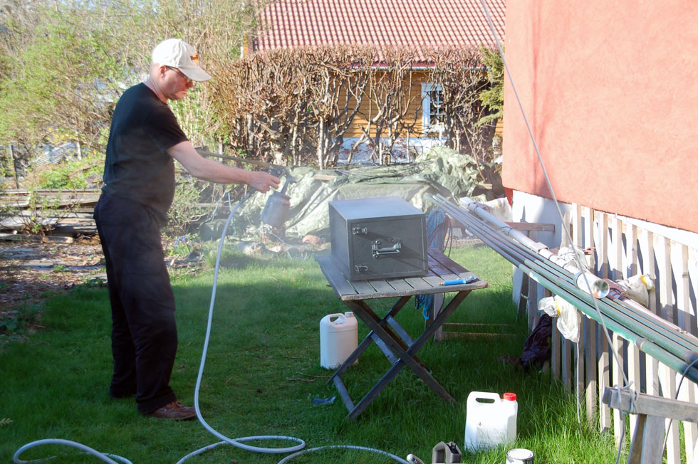
Painting box to KwEa with compressed air spray. RAL7016 or
RAL7017.
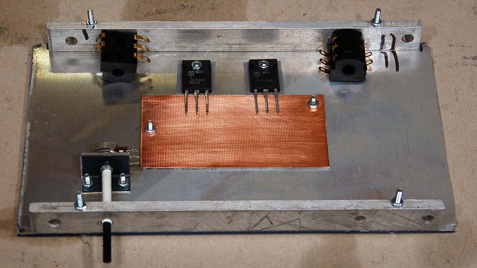
| KwEa have very large
headroom on the audio out. It's easy to get hearing damage caused by powerful audio amplifier. I have therefore designed this 2.5 Watt amplifier. Here I have started at the work. Another option is to use a compressor / limiter before the audio amplifier. |
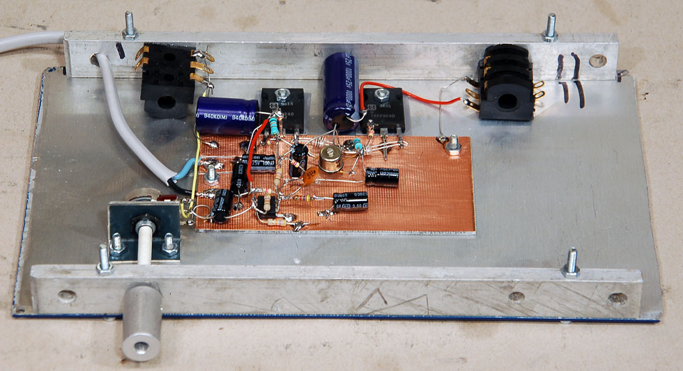
I build the amplifier on a circuit board.
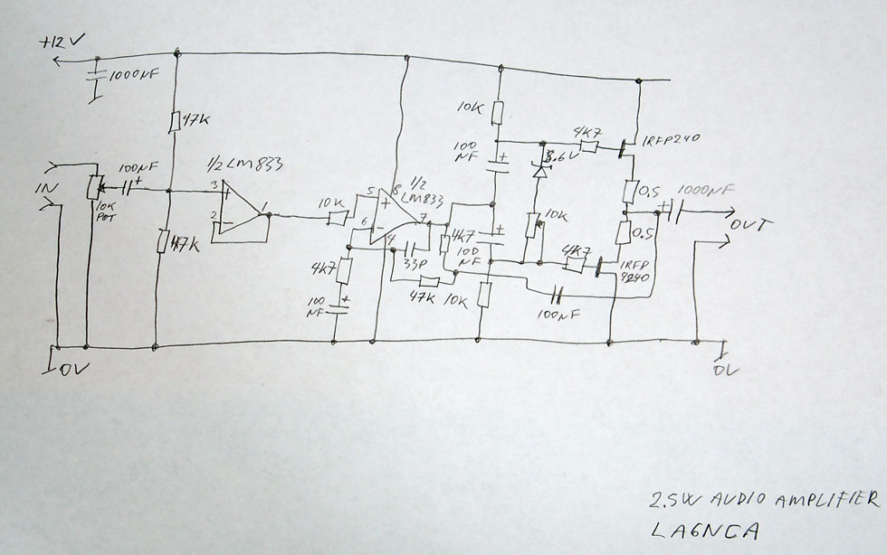
| The amplifier is built
around an LM833 op amp. Two mosfet transistors provide enough output power. |
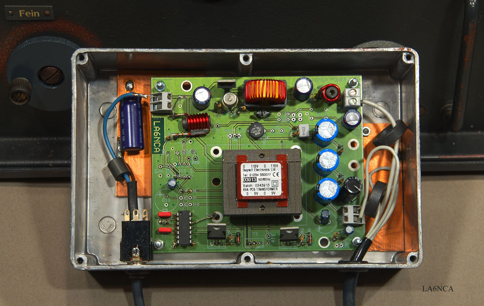
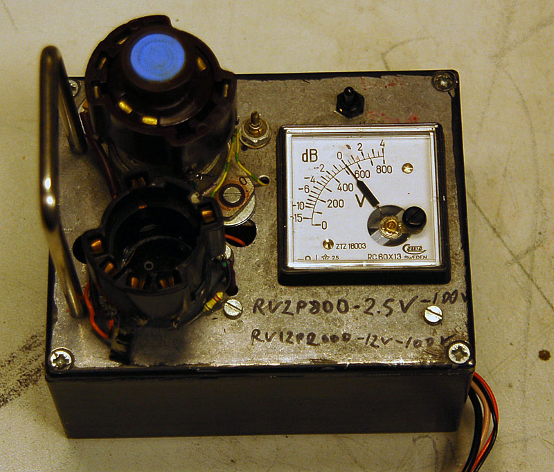
| This is my KwEa power. Input is 12 volts DC. Output is 2 volts DC and 90 volts DC. |
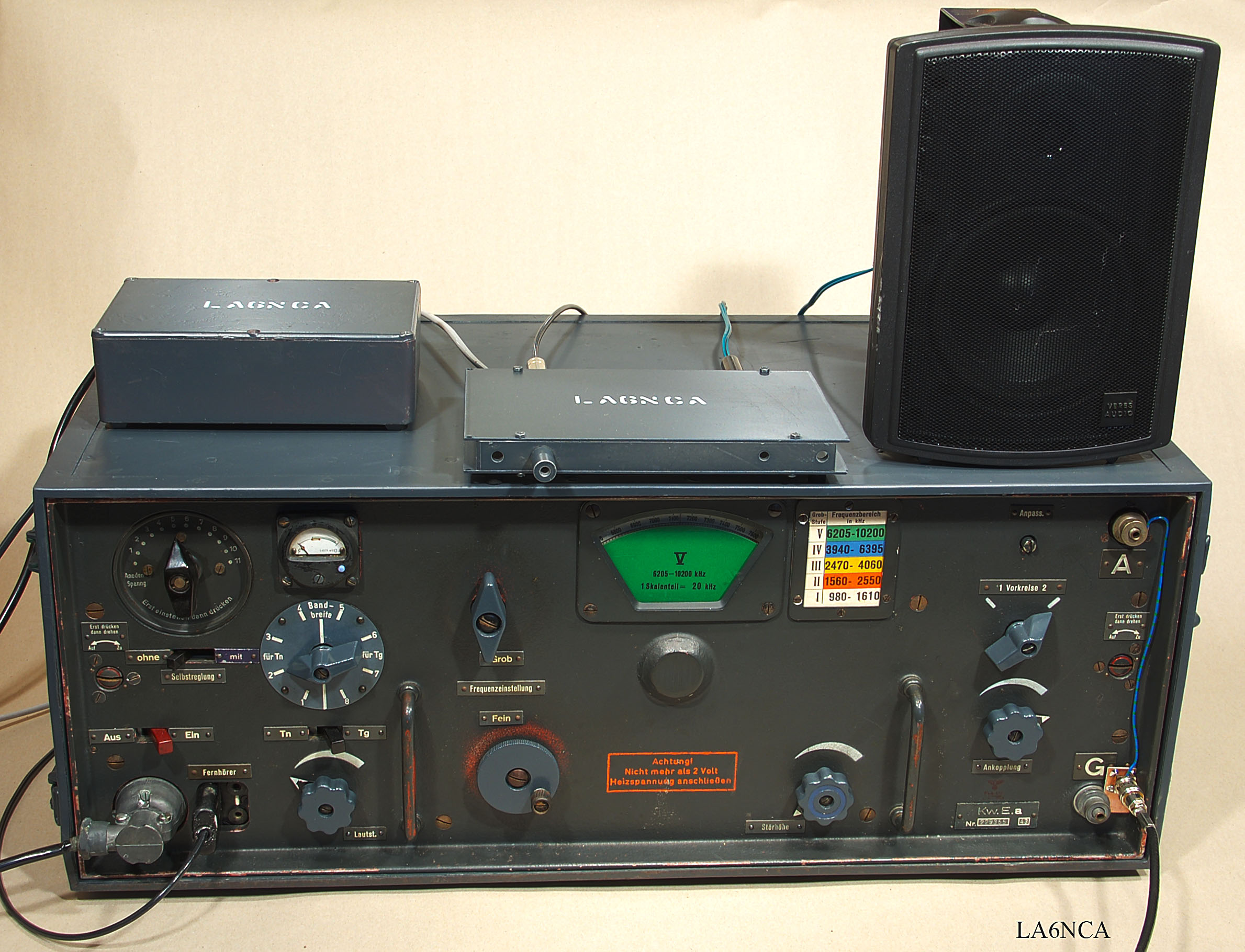
Here is KwEa finished.
kwea34a.jpg
kwea35a.jpg
kwea37a.jpg
Here are all finished. Power, amplifier, monitor and KwEa
receiver.
See how I connect the antenna with a BNC.