 |
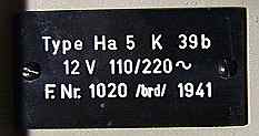
LA6NCA RADIO PAGE Ha 5k 39b (HAGENUK) |
 |
|
LA6NCA RADIO PAGE Ha 5k 39b (HAGENUK) |
|
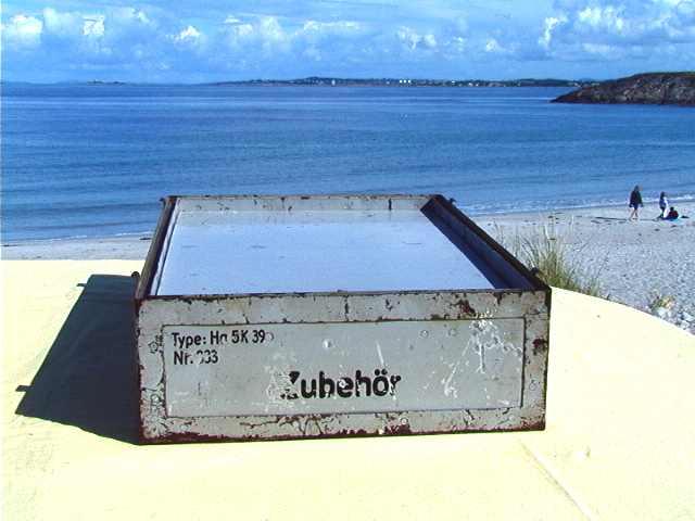
HD PHOTO
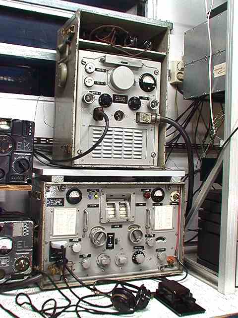
I have mounted all my Hagenuk. Has worked for weeks to get all
100% OK.
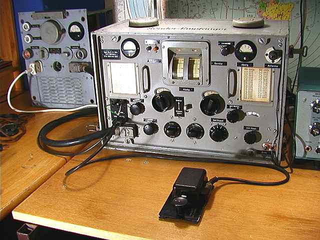
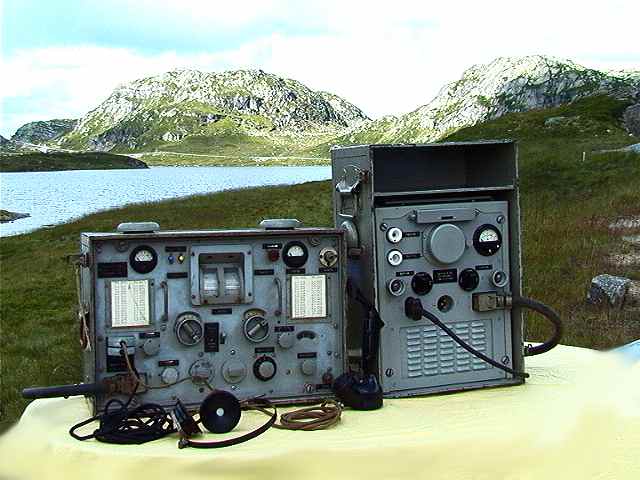
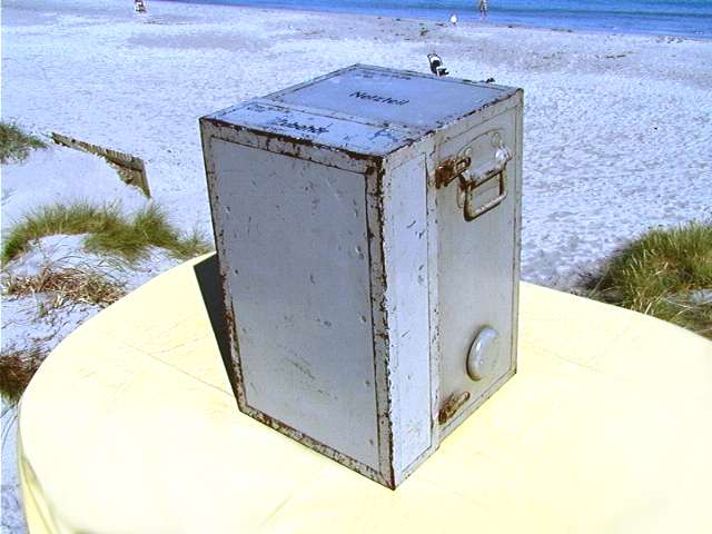
Here is my Ha5k39b.
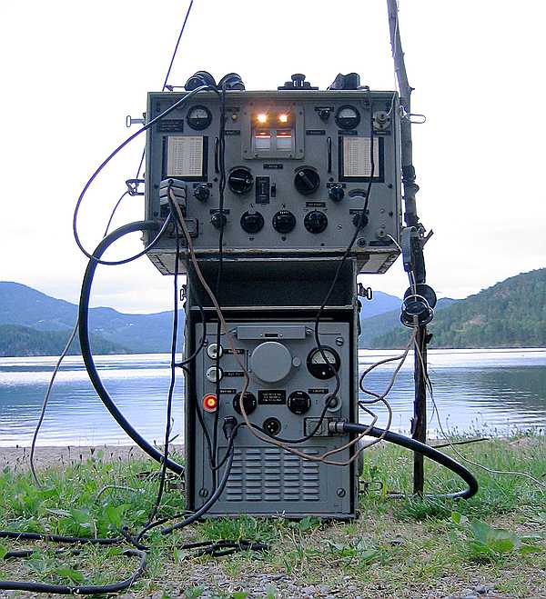
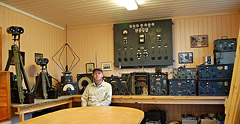
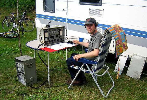
It is here ready for operation on the beach
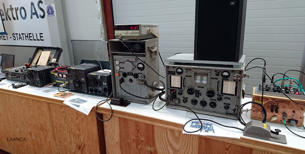
From my exhibition at hobby fair in Langesund.
Grenland Group of NRRL has a radio amateur exhibition.
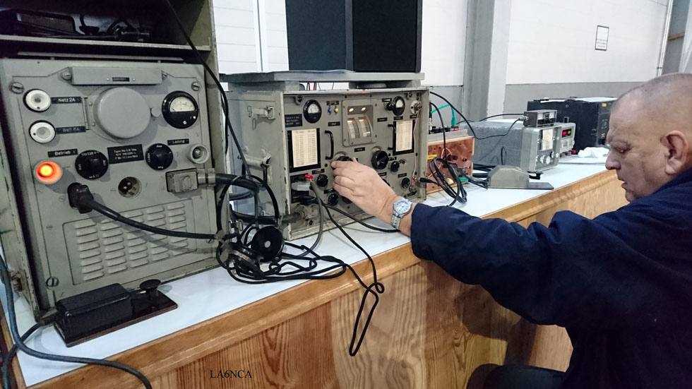
OM LA8IG operate CW on the old transceiver
Here
I have the first contact on CW with my new Ha5k39b.
The station worked is LA5FH in Larvik, Norway. Distance is 100
km.
| Technical data transmitter: Output power phone, A3:.............. 1.5 Watt Output power CW, A1:................. 5 Watt Frequency range: .......................... 2 MHz - 5 MHz Keying: ......................................... Fangitternøkling i oscillator and PA. Tube, oscillator: .............................RV12P2000 Tube, PA: .......................................RL12P10 Modulator tube: ............................ RV12P2000 Regulator tube: ............................. GR150A Technical data receiver: Type: ............................................. 3 tube TRF-Receiver. Tube 1: ............................................HF input amplifier with two resonant circuit Tube 2: ............................................ Regenerative detector. Tube 3: ............................................ Audio amplifier. Frequency range: ........................... 2 MHz - 5 MHz Sensitivity A1 (CW): ..................... 4 uV Sensitivity A3 (AM): ..................... 40 uV Audio range: ....................... 300 - 3000 Hz. |
New Video
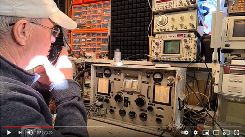 German WW2 Kriegsmarine Radio, Hagenuk Ha5K39b used on AM |
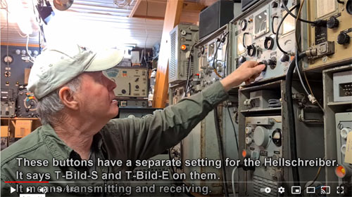 FELD HELL, WW2 Hellschreiber and Hagenuk Ha5K39b in use |
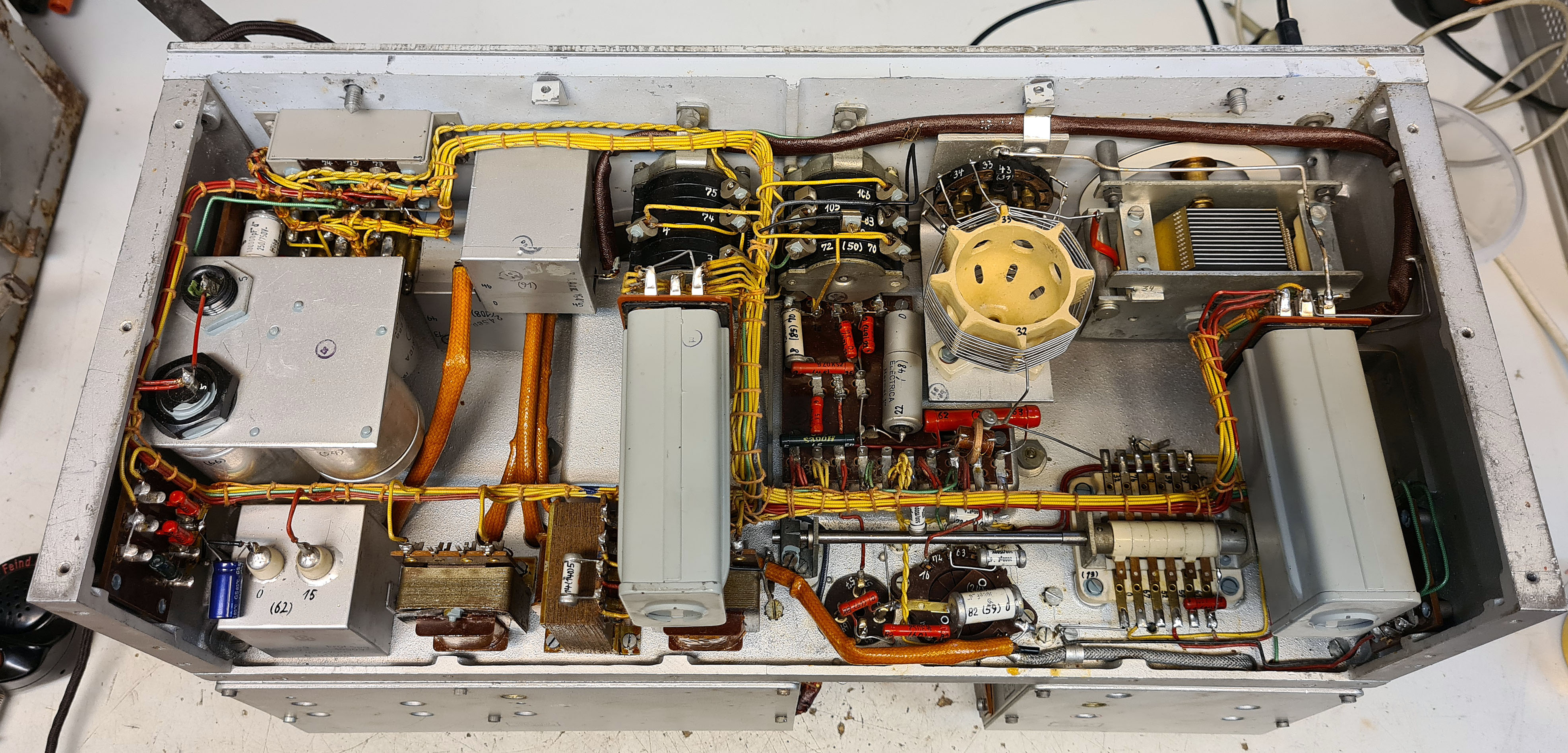
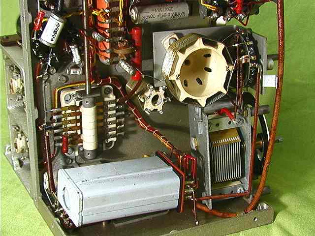
HD PHOTO
Here we see the underside of Hagenuk
Ha 5k 39b (HAGENUK) nr. 2
Ha 5k 39b (HAGENUK) nr. 1

 1
1
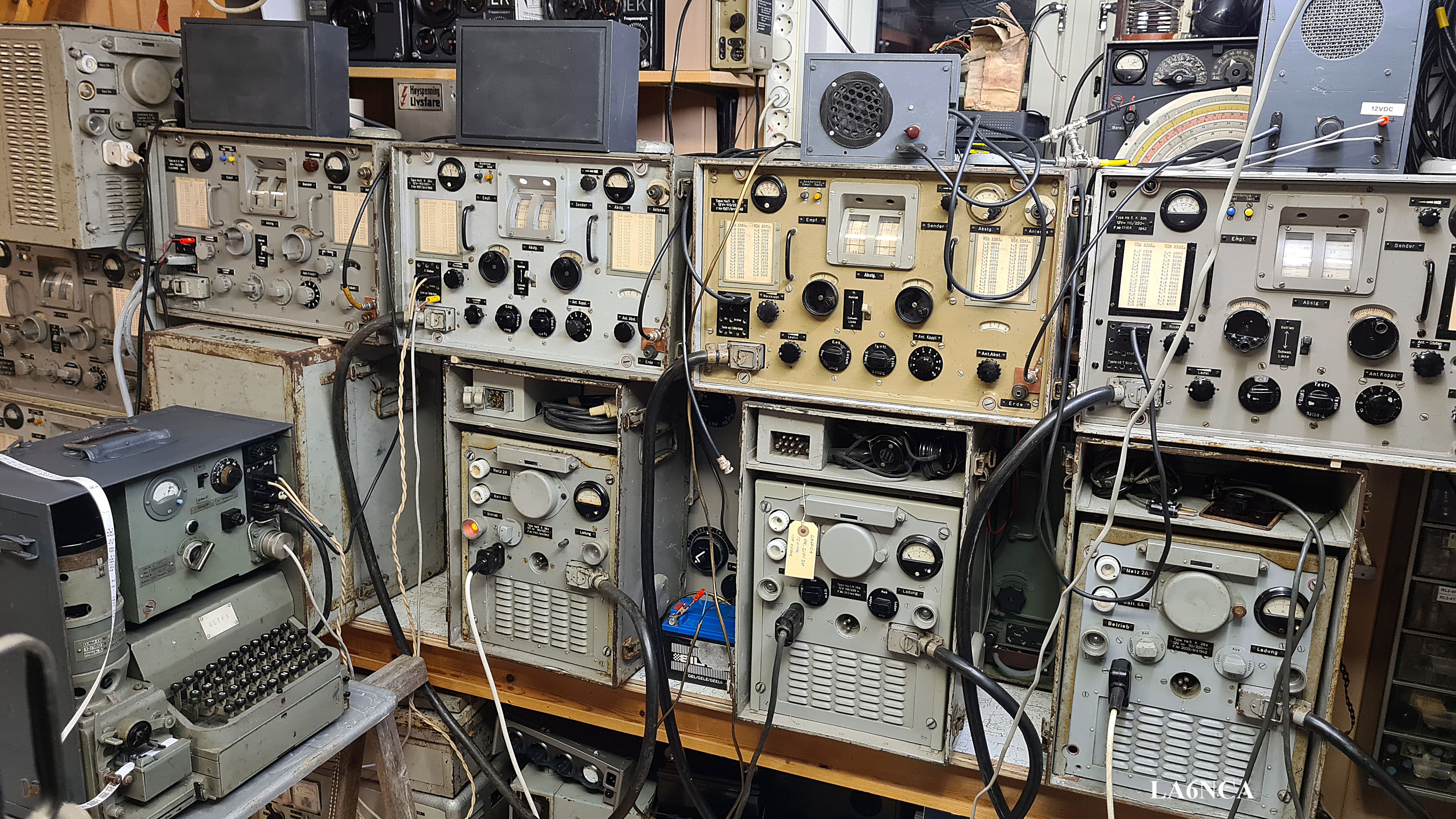
This is a 5 Watt
transceiver for the frequency band 2.0 - 5.0 MHz. Modulation is
CW or AM.
 2
2
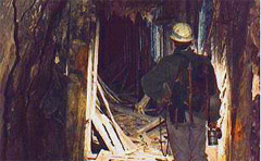
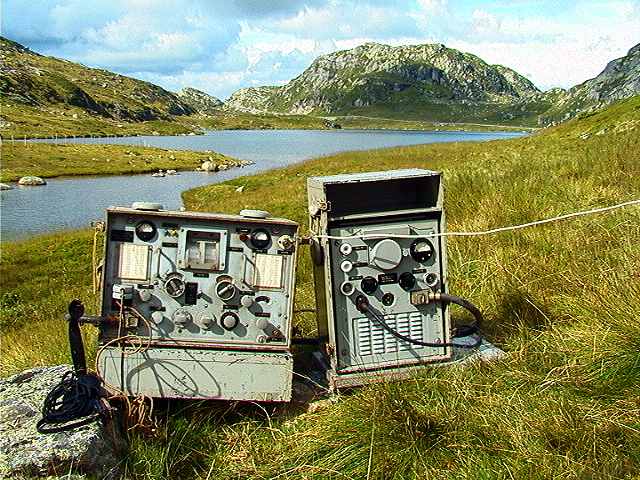
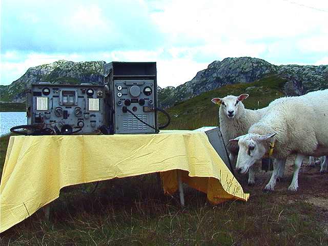
Here is the station
operative in the Norwegian mountain.
 3
3
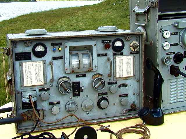
Transceiver unit.
 4
4
Here is the radio
station in the Norwegian mountain.
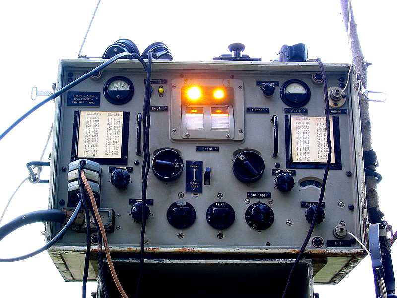
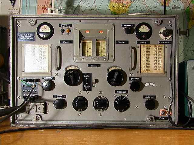
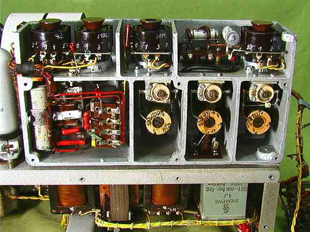
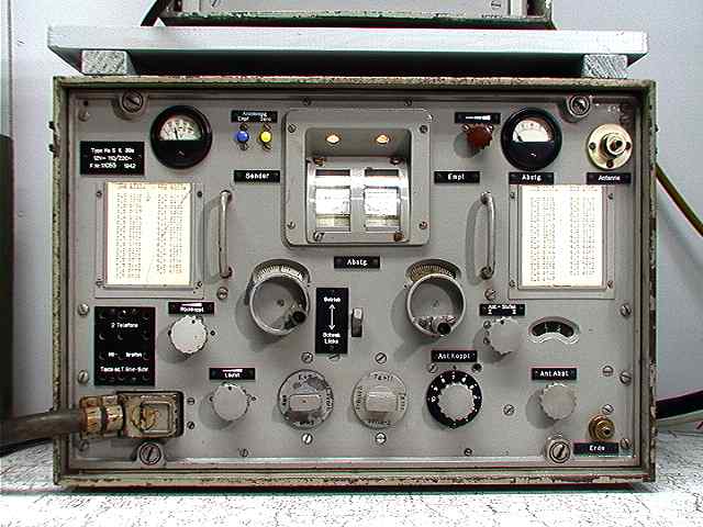
INSIDE THE TRANCEIVER
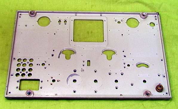 15
15
The front plate is
made of moulded metal.
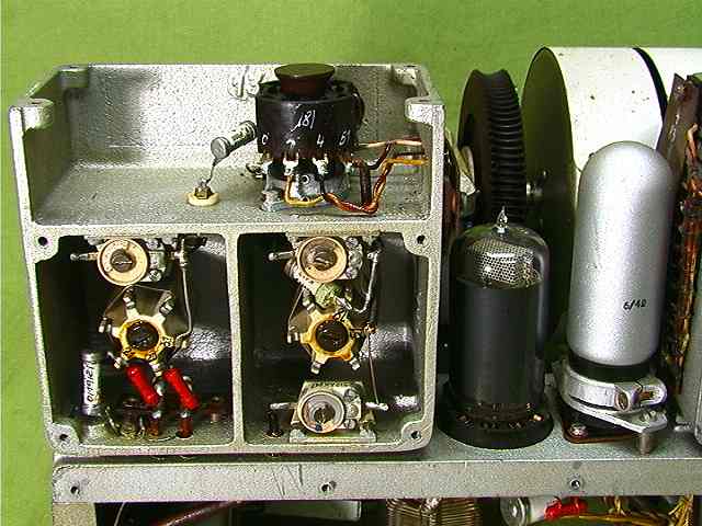
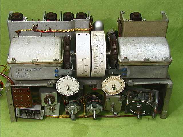 16
16
| Behind the front plate. Receiver to the left. Transmitter to the right |
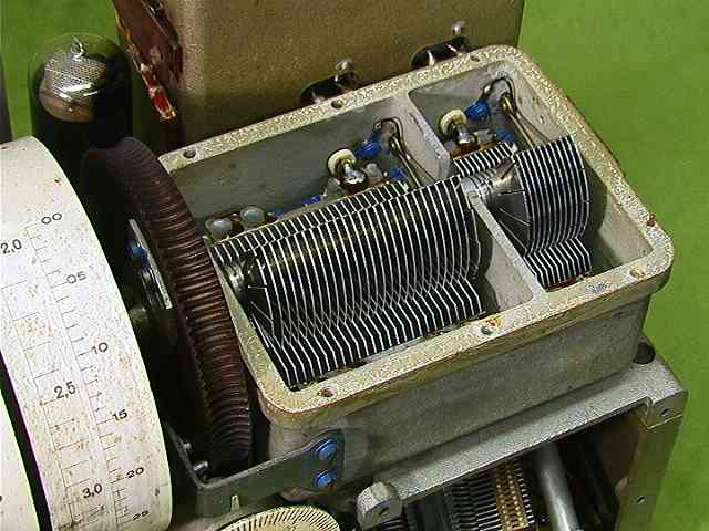
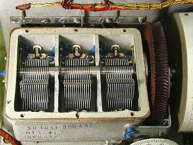
 17
17
| Here is the transmitter
tuning capacitor mounted in a moulded case. Ball bearing is used. |
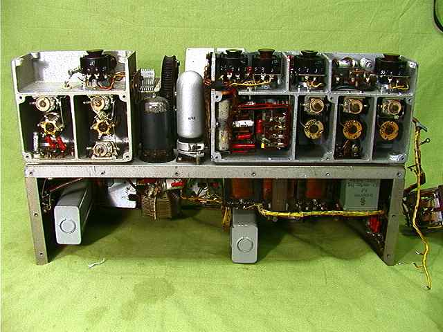 18
18
Transmitter to the
left. Receiver to the right.
 19
19
Transmitter capacitor.
 20
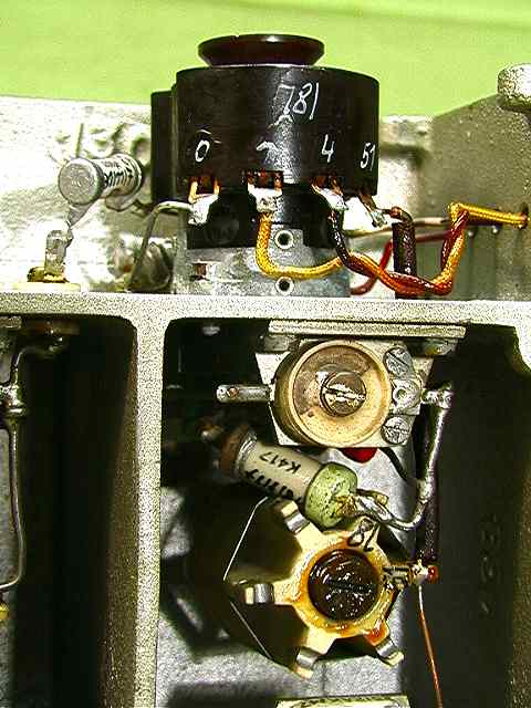
20
Here is the
Transmitter oscillator with RV12P2000.
 21
21
| The oscillator is to the
left. RV12P2000. An frequency dubbler is used. Output tube is RL12P10. |
 22
22
.Receiver capacitor.
 23
23
Receiver.
 24
24
Transmitter antenna
tuner.
After restoration
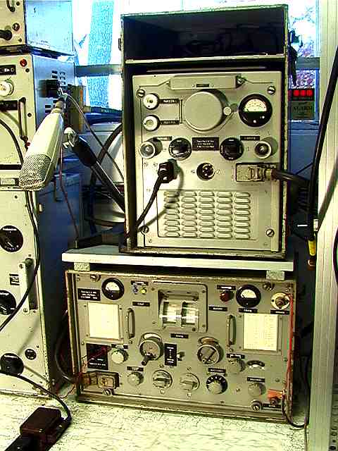
POWERSUPPLY
 5
5
Power-supply with the
equipment box.
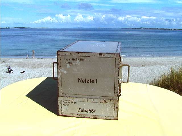 6
6
The power-supply has
serial number 963, and the equipment box has serial number 333.
 7
7
| Microphone, headphones and
key is stored over the power supply. The power has 12VDC and 230VAC input. When 230VAC is used a 12Volt accumulator can be charged. |
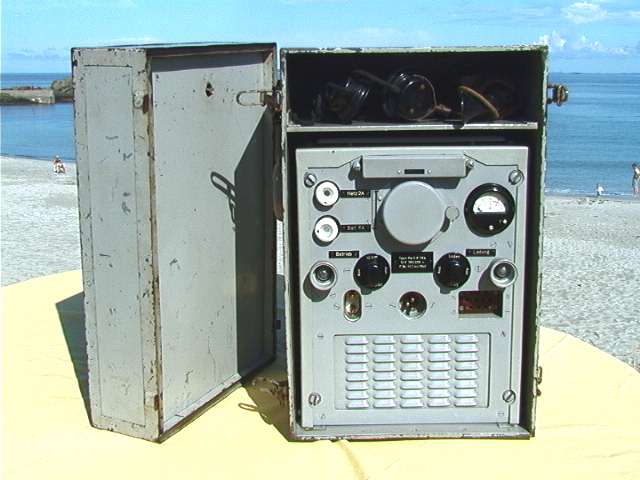
 8
8
The power with inner
cover and outer cover.
 9
9
The power has two
transformers. One for radio operations and one for accumulator
charging.
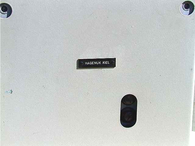 10
10
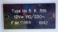
"HAGENUK
KIEL"
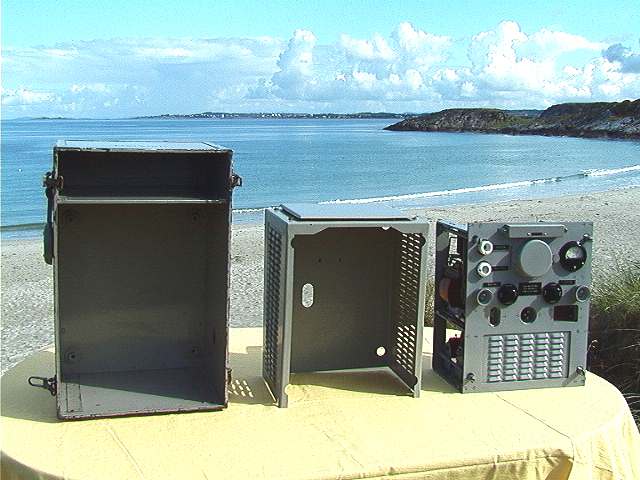
 11
11
Equipment box is
placed in the power cover.
Serial number 333.
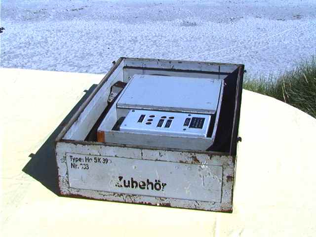 12
12
Here is the equipment
box with frequency calibrator and power cable.
Here are also spare tubes and other small parts.
FREQUENCY CALIBRATOR
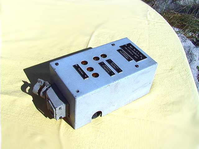 13
13
The frequency
calibrator has a 3 MHz XTAL oscillator. Booth the
receiver and transmitter can be calibrated with this unit.
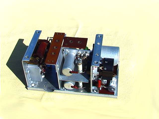 14
14
The XTAL oscillator
uses the RV12P2000 tube.
BACK