|
|
 |
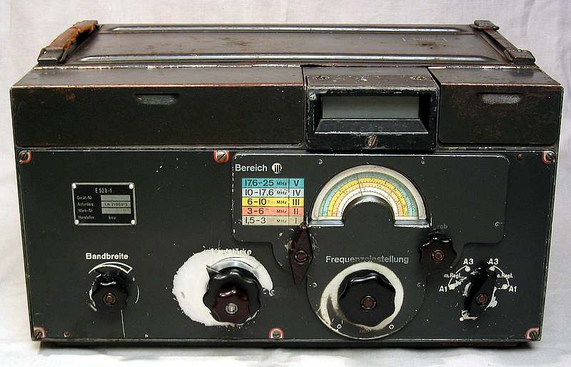
E52b-1
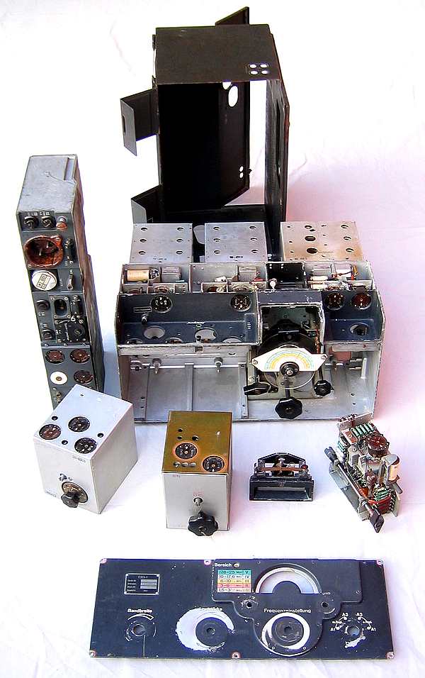
All the main part in the receiver can easy be removed from the
chassis.
POWER
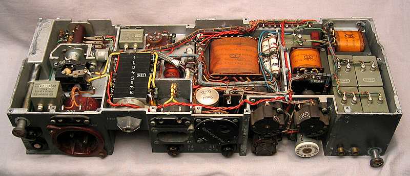
MF
MF XTAL filter.
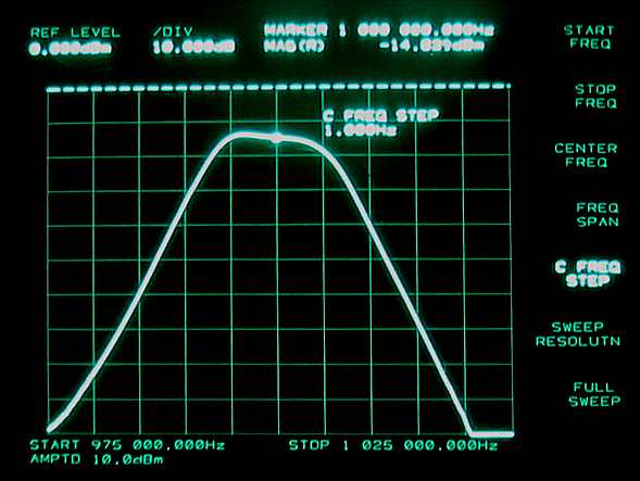
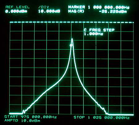
MF filter frequency response. Max bandwidth.
Vertical resolution is 10dB
Horizontal resolution is 5 kHz
MF filter frequency response. Min bandwidth.
Vertical resolution is 10dB
Horizontal resolution is 5 kHz
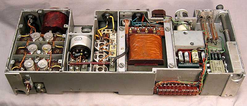
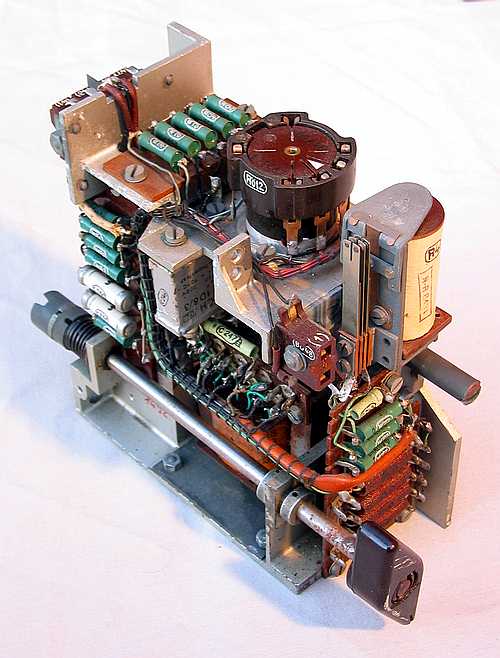
DETECTOR AND BFO
BFO and detector section before restoration.
The BFO control knob vas removed on all Kõln before the war was
ended.
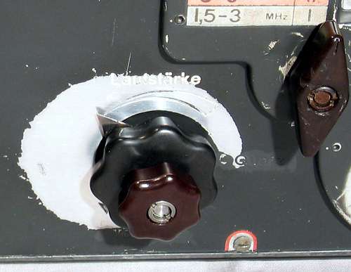
Here is the BFO control knob replaced. This control is important
for operating
on 80 and 40 meter ham band. The BFO control switch inn an out
the USB XTAL.
The control can also set the USB and LSB BFO frequency with a
continuous variable oscillator.
When the BFO control vas removed both the knob and the internal
wiring to the switch U19 vas removed.
When I replaced the knob I replaced also the wiring to the right
section of the switch. I connected two
wires from the XTAL to the switch. The BFO is working OK without
the left section connected to the U19.
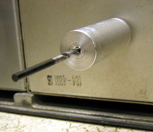
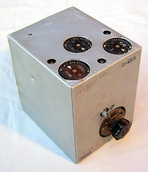
Drilling tool for the BFO knob replacement.
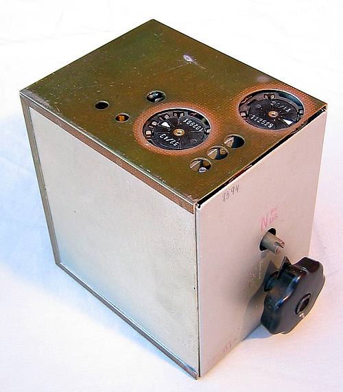
AUDIO AMPLIFIER
Audio amplifier.
MECHANIC
Here is also the paint removed
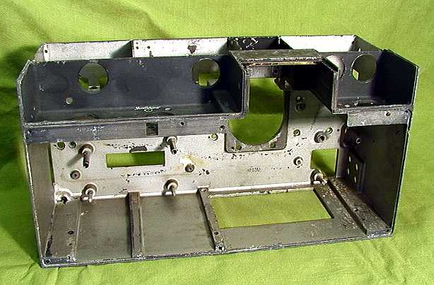
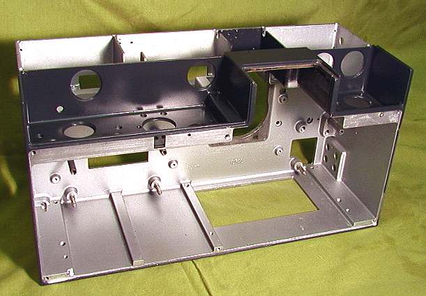
E52b has a very advanced die
cast chassis.Here are all components removed.
Most of the paint is also removed, and it is washed in a washing
machine.
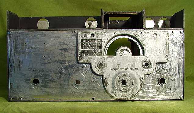
Front side.
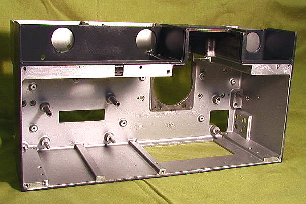
Here with new paint.
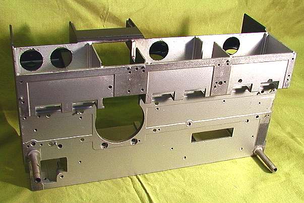
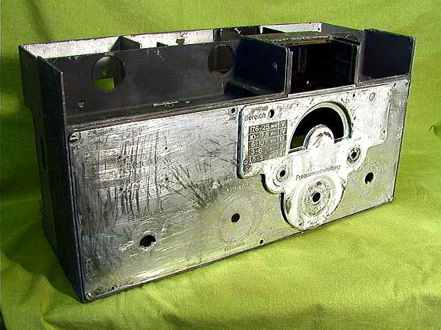
Back side.
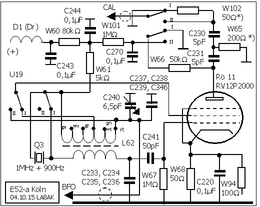
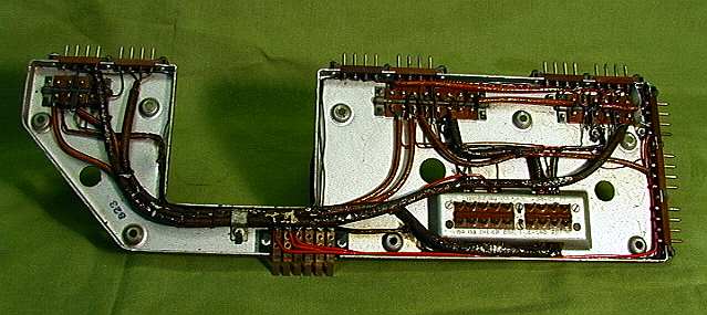
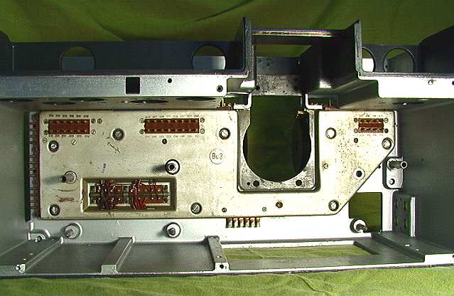
BACKPLANE
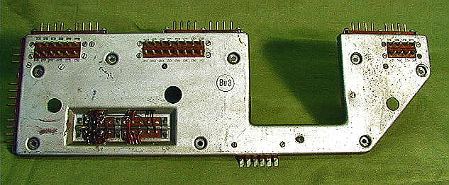
This is one of the first back
planes in any receiver. All the interconnection in the receiver
is in here and all units in the receiver are plugged in the back
plane.
Inside the backplane.
Here is the back-plane mounted.
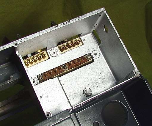
Here are the back-plane connections for mixer/oscillator.
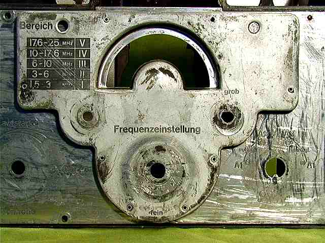
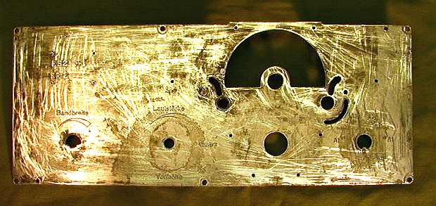
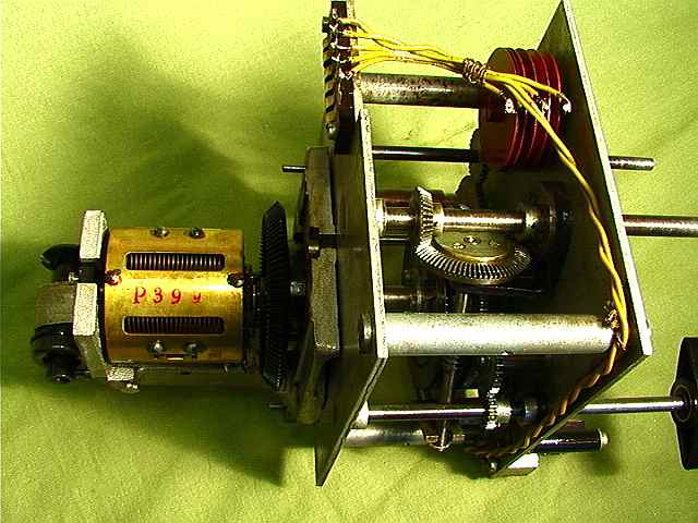
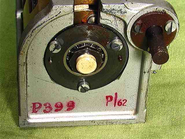
TUNING MECHANISM
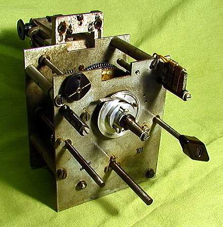
Tuning mechanism.
Tuning mechanism.
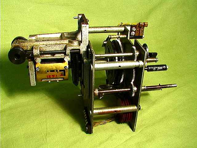
Tuning mechanism with oscillator capacitor.
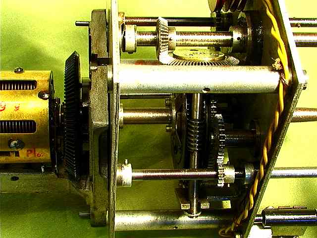
Here is the frequency adjustment mechanism.
All wheel have anti backlash mechanism.
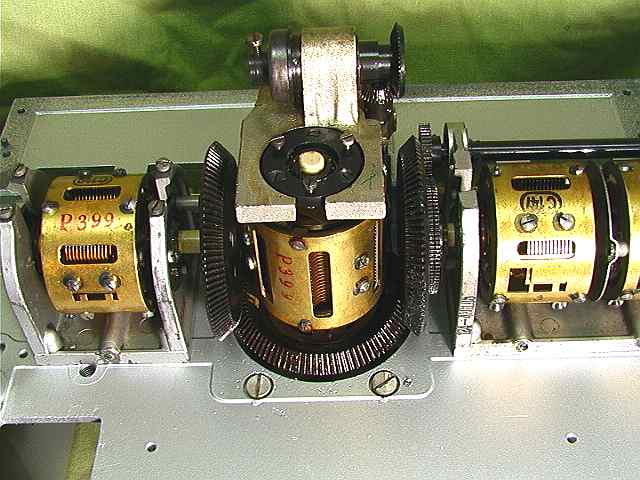
TUNING CAPACITORS
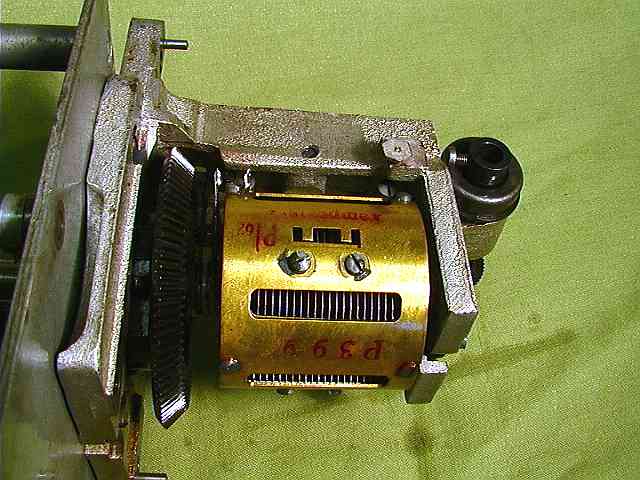
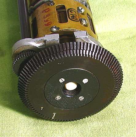
Here is the oscillator tuning capacitor. C148.
C149, Here is the setscrew for the rotation
fastener (below capacitor)
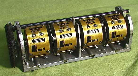
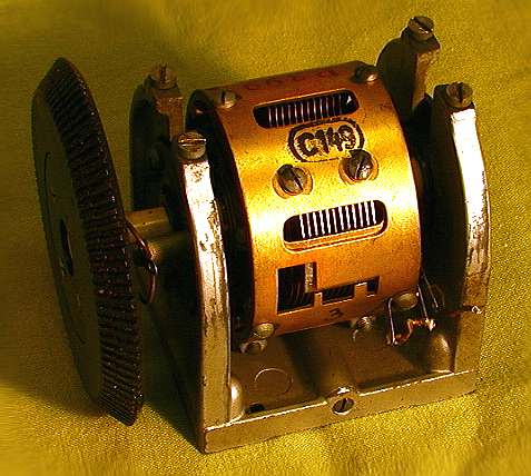
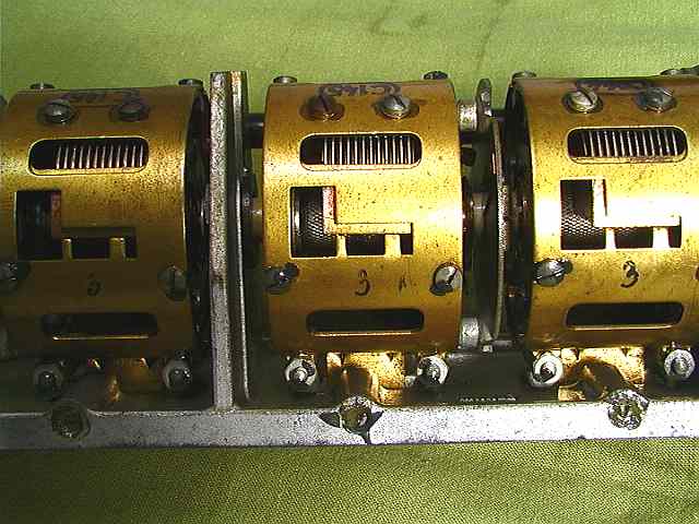
Four of the six tuning capacitor. C144, C145, C146 and C147.
Here is the anti backlash mechanism on each capacitor shaft.
The cogwheel is mounted on a porcelain shaft.
The tuning capacitors are extremely advanced.
Rotor is placed on a porcelain shaft.
Stator is placed on two ball bearings on the porcelain shaft.
This will give an extremely accuracy.
Here is a porcelain fasteners witch prevent the stator to rotate.
The stator can move in all direction as a result of temperature
variations.
The capacitors value will not be changed with this design.
The variable capacitors have ball Bering from
SKF.
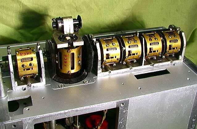
Six capacitors are connected together in the frequency tuning
mechanism.
From right:
1 – C144, Antenna input tuned circuit...............
2 – C145, Grid circuit on first RF amplifier........
3 – C146, Anode circuit on first RF amplifier.....
4 – C147, Grid circuit on second RF amplifier...
5 – C148,
Oscillator.........................................
6 – C149, Anode circuit on second RF amplifier
Here are the tuning capacitors mounted.
Position of capacitors is extremely accurate. (Better than 1/100
mm)