|
|
|
|
|
|
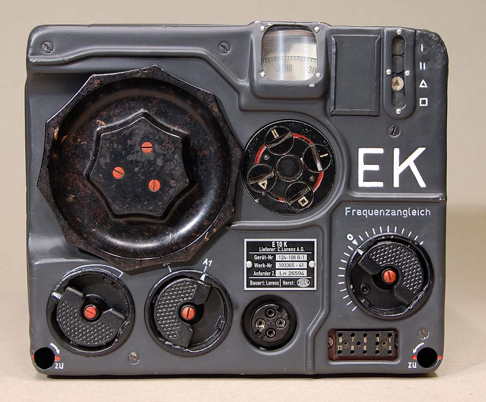
E10K is the short wave
receiver in the FUG10 system. The FUG10 system was developed in
1936 – 1937,
and was from 1939 standard radio system in most of
Luftwaffe’s bombers.
Four preset
radiofrequencies can be programmed with the wheel under the dial.
Latest technology with
the tube RV12P2000 was used in all functions in the receiver.
The receiver can be
replaced in less then 30 seconds with the unique mounting system.
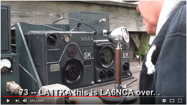
Film, AM sending on Fug10
LA8AK’s
block diagram.
| E10K HF receiver Frequency range: 3.0 – 6.0 MHz IF = 1460 kHz. Power: 12V , 230V Measures: H = 180 mm, W = 220 mm, D = 200 mm Weight: kg |
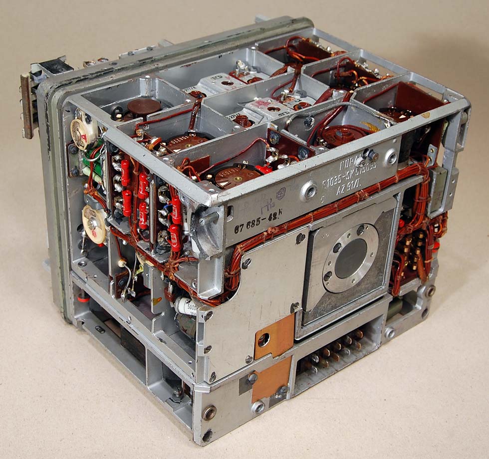
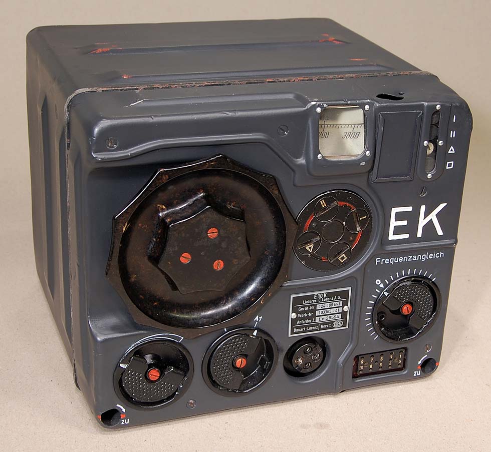
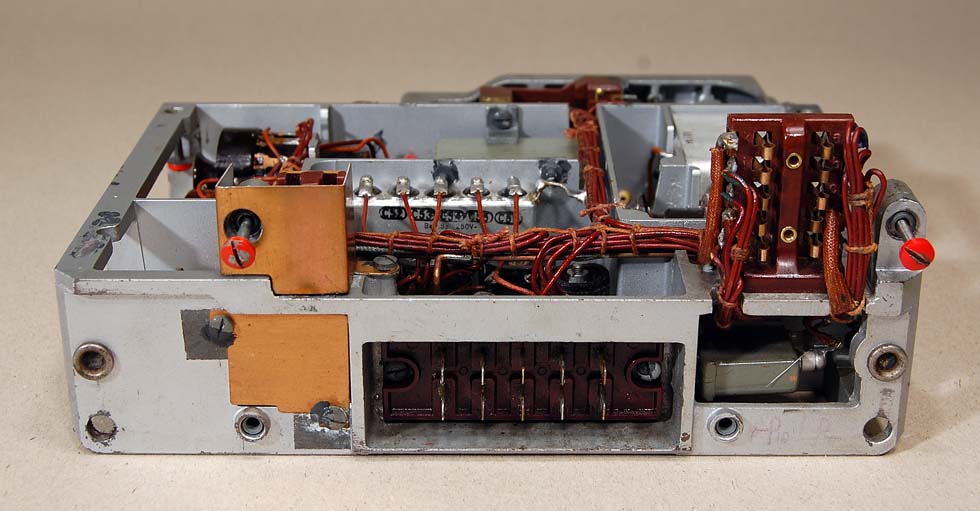
Here we can see the fine
mechanical molding technology used in this radio.
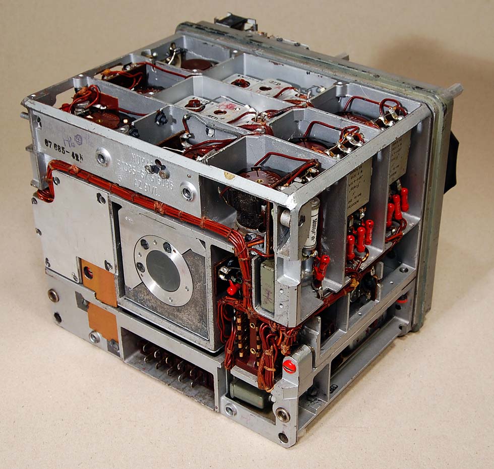
Look at the advanced
casting technique and cable guide. This is the German WW2
technology on top.
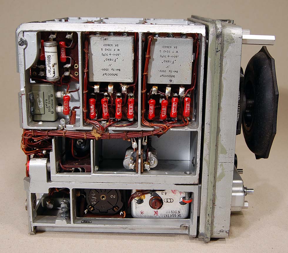
Left side. The BFO
oscillator with RV12P2000 is located in the bottom of the photo.
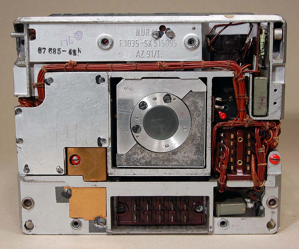
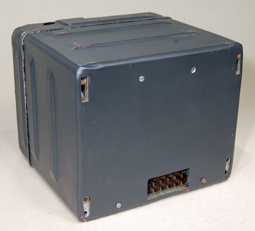
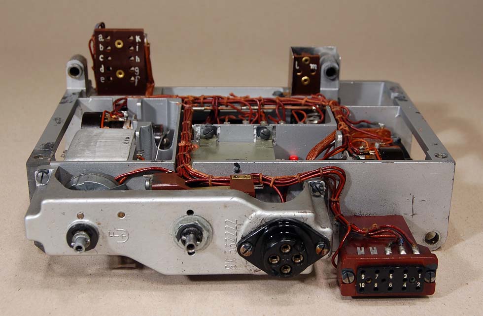
Rear side. Here is the 10 pin connector with antenna, power and
audio signals.
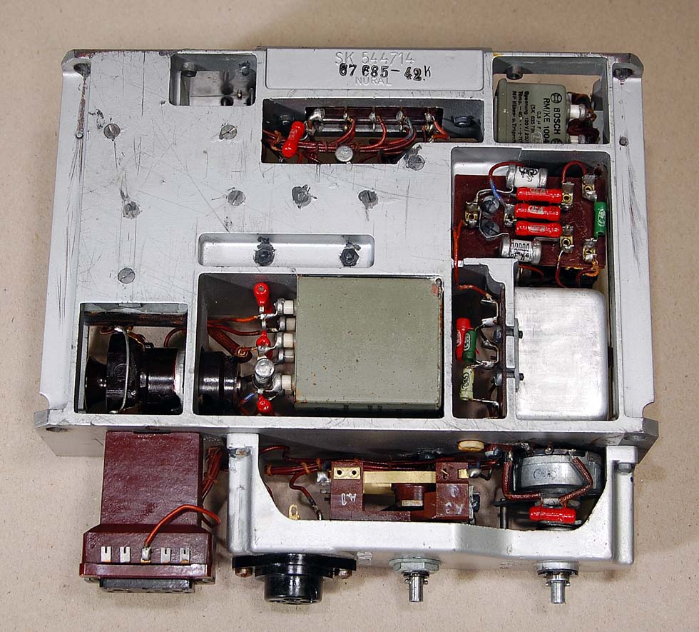
The audio amplifier is
located in the lower section.
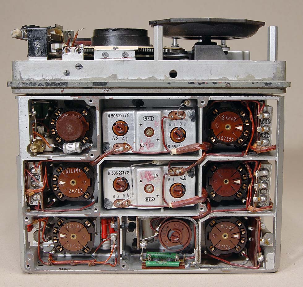
Upper side. Her is both
RF an MF circuits.
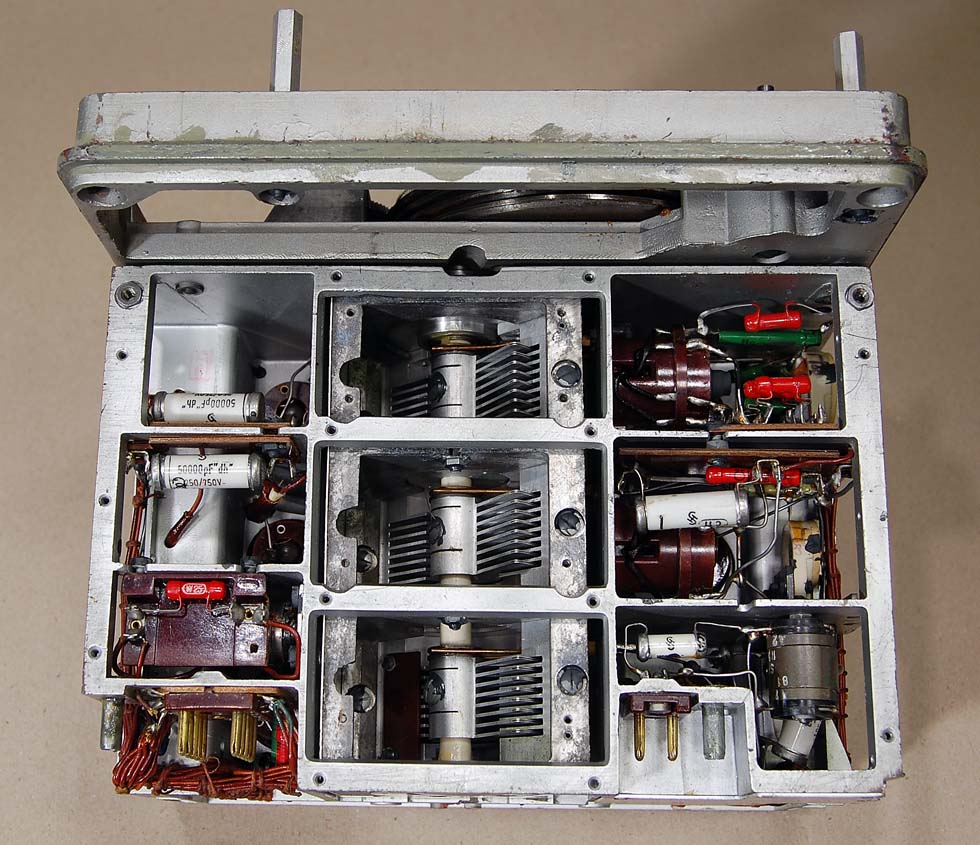
Underside of the RF
section. Here is the fantastic tuning capacitor.
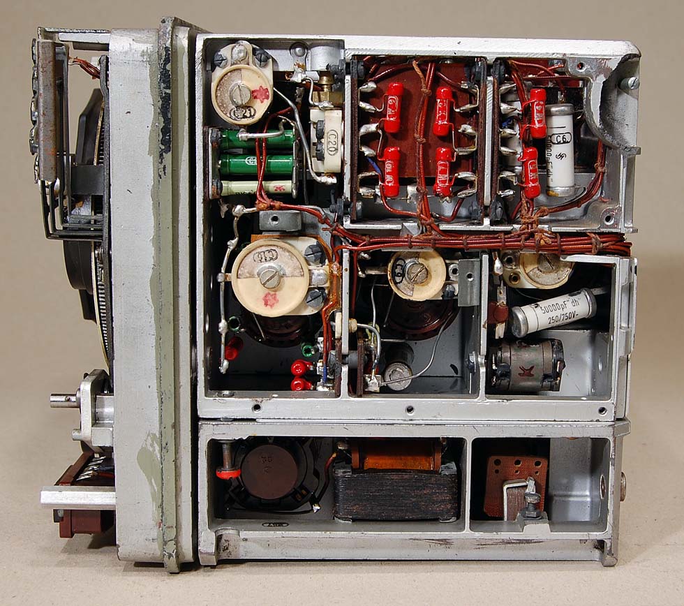
AUDIO AND BFO
SECTION.
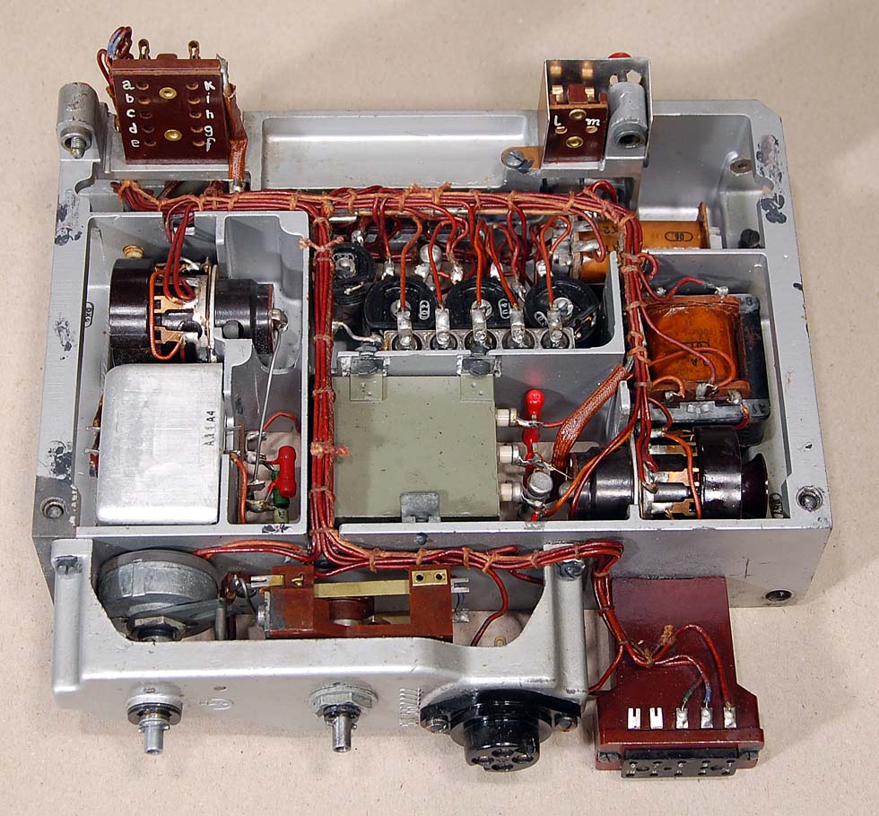
Here is the lower section of EK10. On the right we have the audio
amplifier. The BFO is to the left.
Here is the technical data for the audio amplifier:
| THD THD, even harmonics THD, odd harmonics THD+N SINAD Output impedance Max level |
0.17% 0.04 % 0.17 % 0.19 % 54 dB -- -- |
Audio module with the headphone connector.
Back side of the audio amplifier.
Underside of the audio amplifier.
-----------------------------------------------------------------------------------------------------------------------------------------------------------------------------------------------------------------
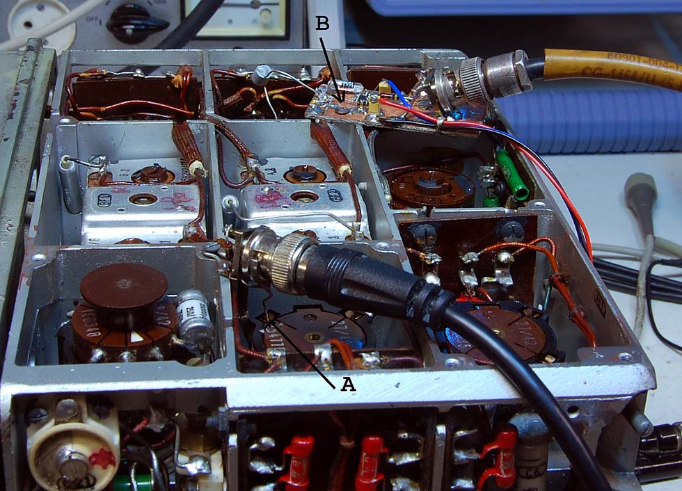
| Measurement of MF filter. (A) is the signal input from measuring equipment. (B) is the signal from the filter and back to measuring equipment. My special measuring probe is in use here. The signal is terminated in a 50 ohm resistors and connected to the input of MF filter with a capacitor of 1 pF. With this equipment, we can measure a dynamic range of 100 dB. |
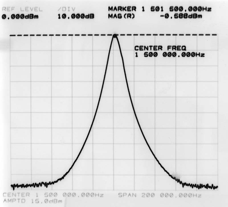
| Here is the curve to the MF
filter. X axis is 200 kHz. Y axis is 100 dB The correct frequency is 1460 kHz and not 1500 kHz that I have calibrated to. The radio works very well with this frequency, too. |
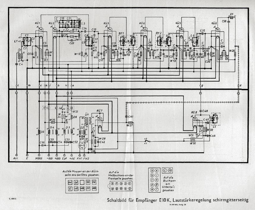
Component
List and high resolution shematic