 |
LA6NCA RADIO PAGE 15W.S.E.a - 15W.S.E.b |
|
|
LA6NCA RADIO PAGE 15W.S.E.a - 15W.S.E.b |
|
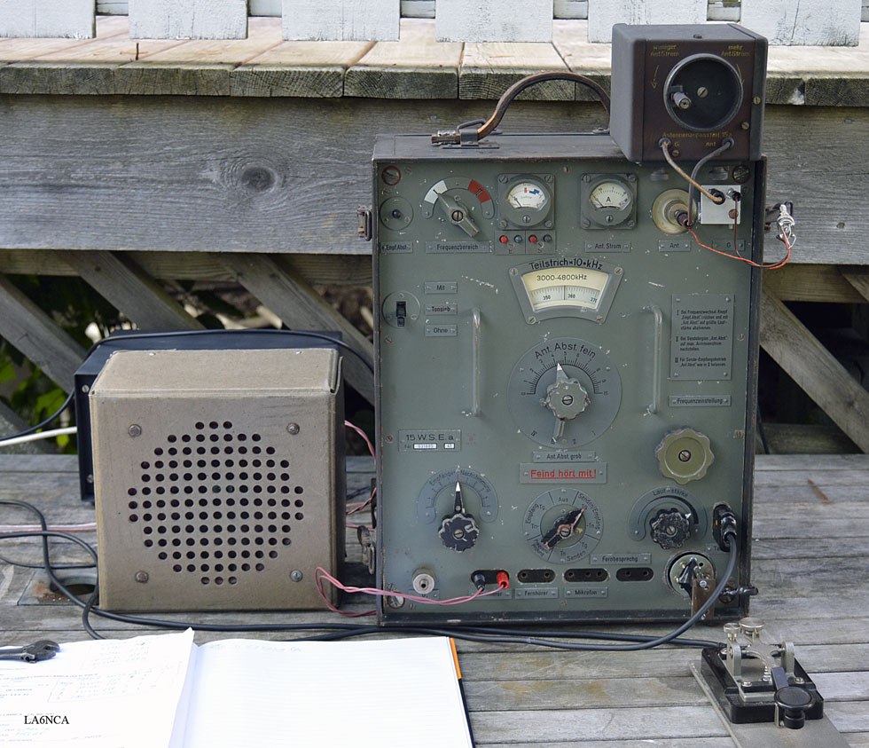
| Picture of
the first QSO with the completed 15WSEa. The first QSO was with the LA8DNA with a distance of 100km. This was a surprisingly good radio. It's amazing fun radio to use. |
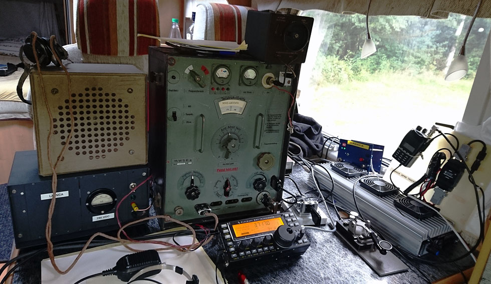
| From my
second QSO. From my motorhome. QSO with LA5MT, distance approx. 100 km. |
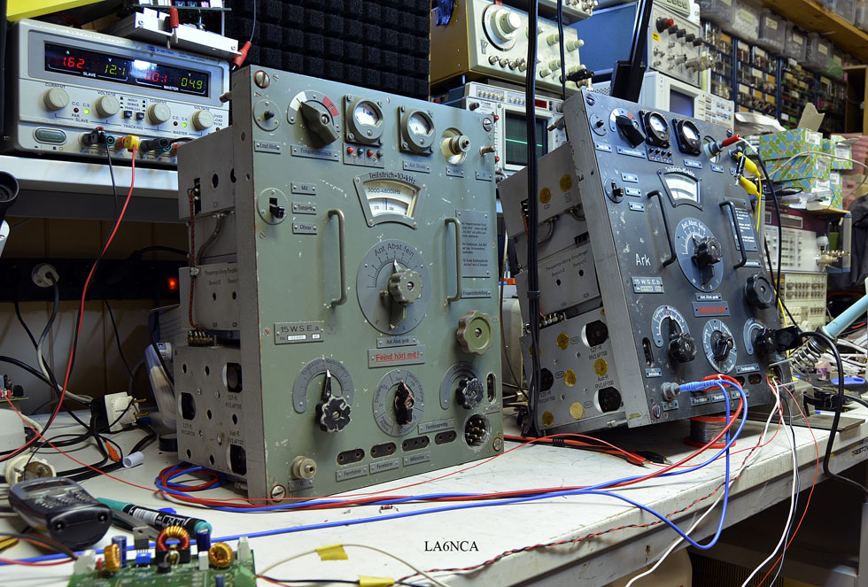
I have after my visit in friedrichshafen started the restoration
of some of my 15WSEa.
The aim is that they should be 100% operational in CW and AM.
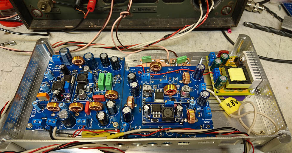
I've started building a power for the tranceiver.
Input voltage 12 to 24 Volt.
Output voltage: 2.4V, 4.8V, 6V, 90V and 330V.
HD 3a.jpg
..................................................................................
IF
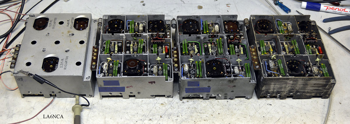
Here are all IF boxes mine ready for calibration.
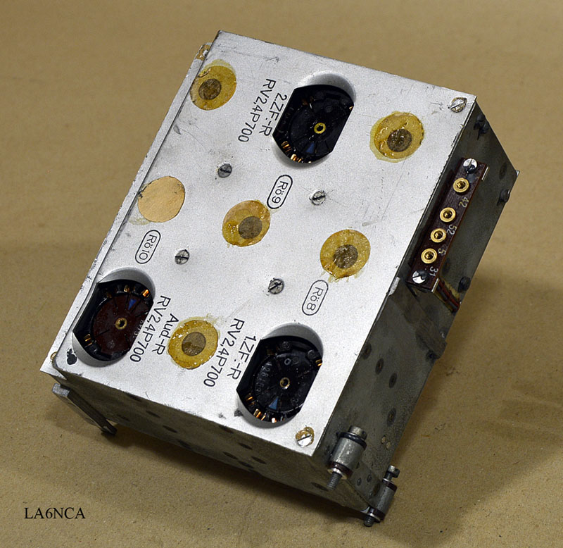
IF stage is mounted in a fantastic nice box.
The shield is very good. Also between stages internally.
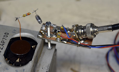
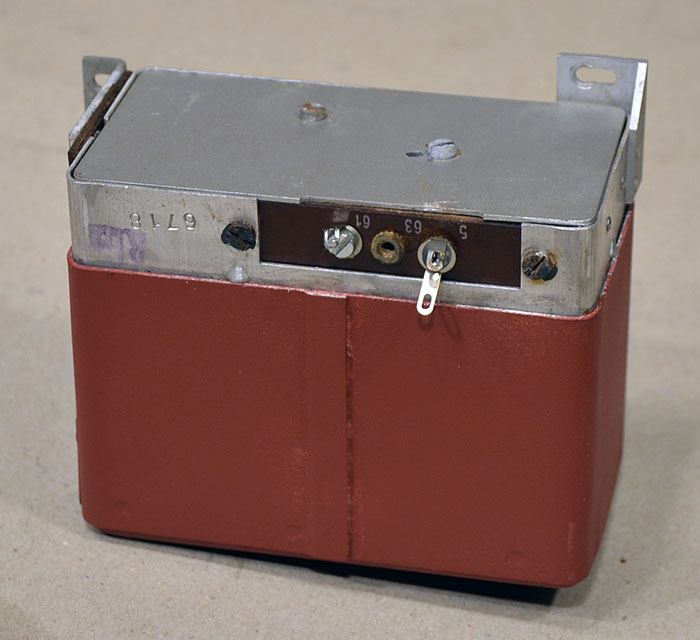
| Here we see voltage contacts
I use during calibration .. 5 is + 2.4V, 31 and 52 are + 100V. 77 on the back side, I have connected -3V 42 is 750 kHz input connector from signal generator. |
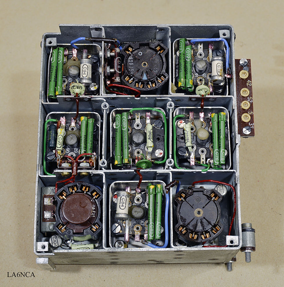
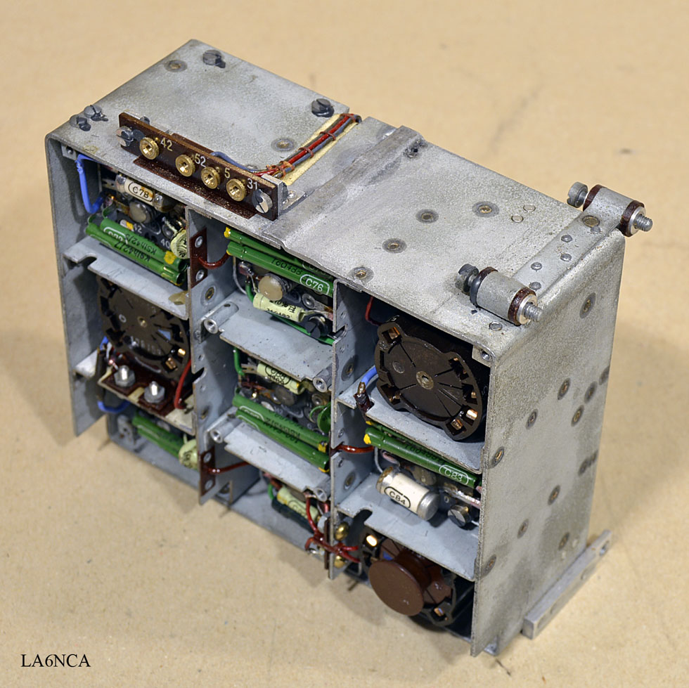
Look at the wonderful shielded rooms in the IF stage.
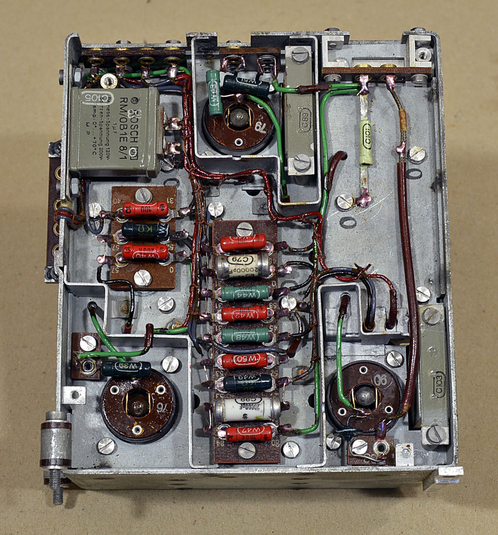
Under the cover on the bottom side is the IF fitted with
resistors and capacitors in a very nice way.
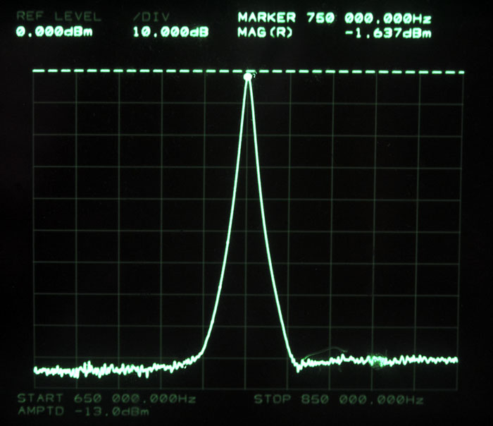
An absolutely stunning IF curve. Noise floor of 90 dB coming from
test leads and not IF stage.
Think 15WSEa is a very good receiver when I see this curve.
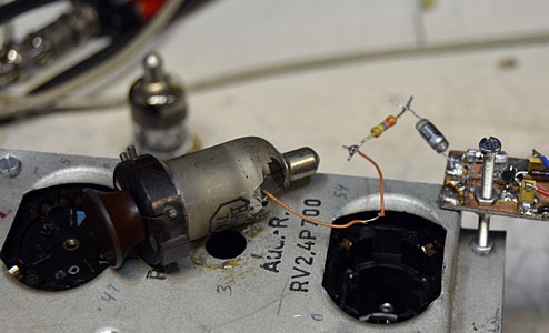
My active measurement probe. I use a broken radio tube for
connection to the probe.
Nr. 090521, Year 1944
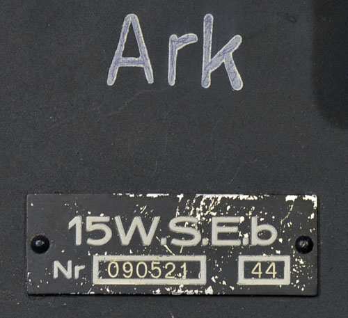
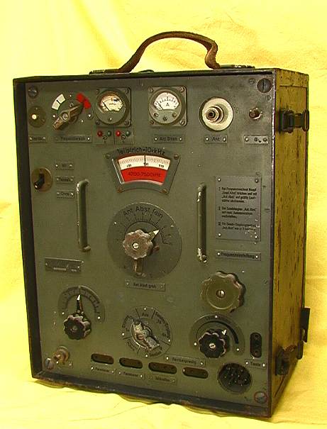
| I will show the restoration
of a late war radio. The lower part of the radio has been in water. |
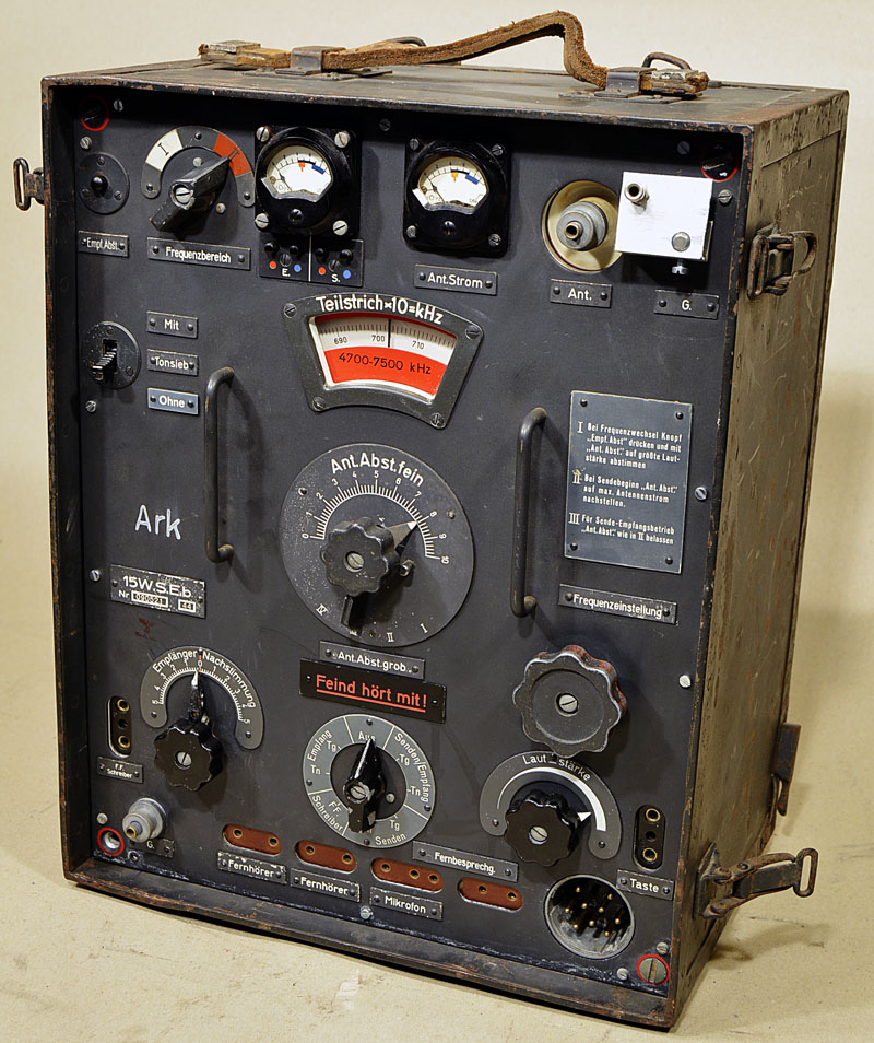
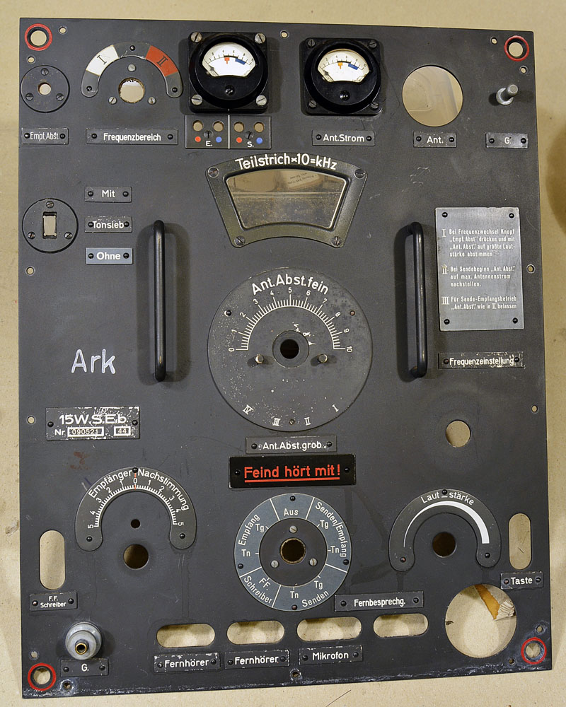
The front plate is washed with water and soap. It became very
nice.
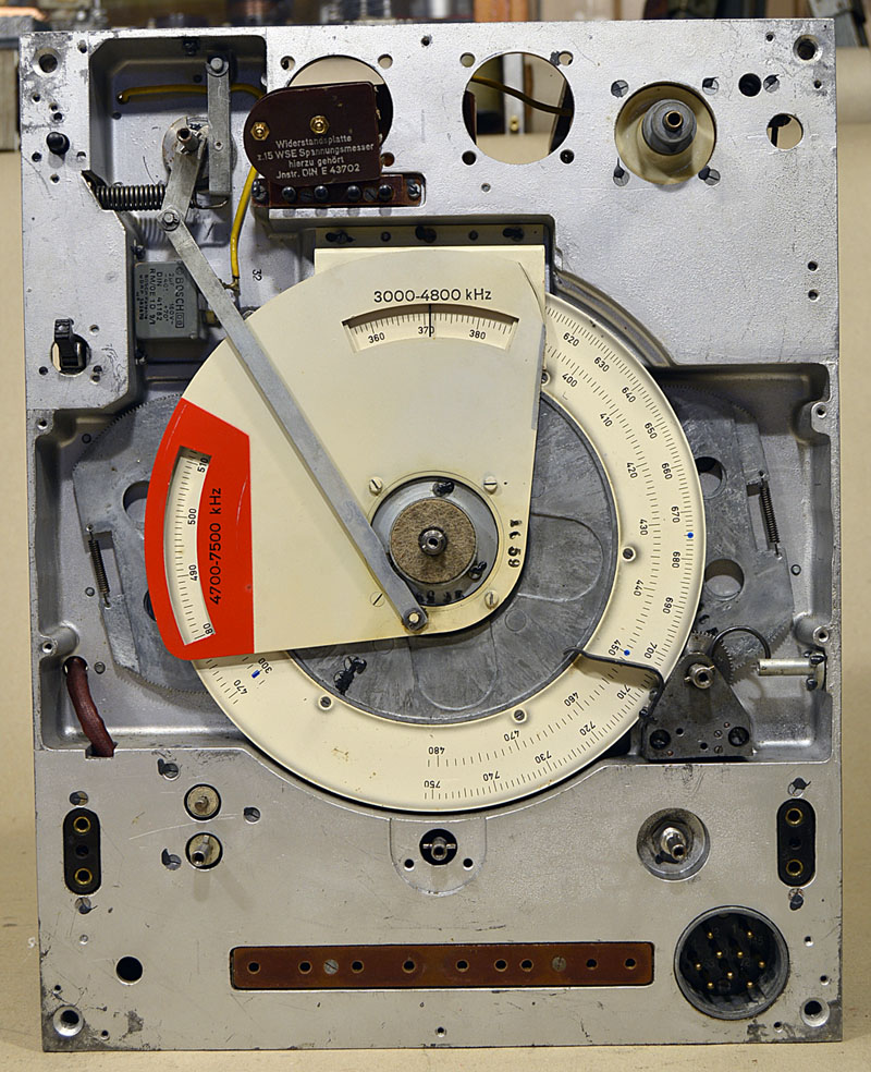
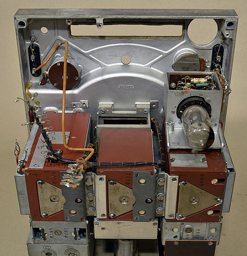
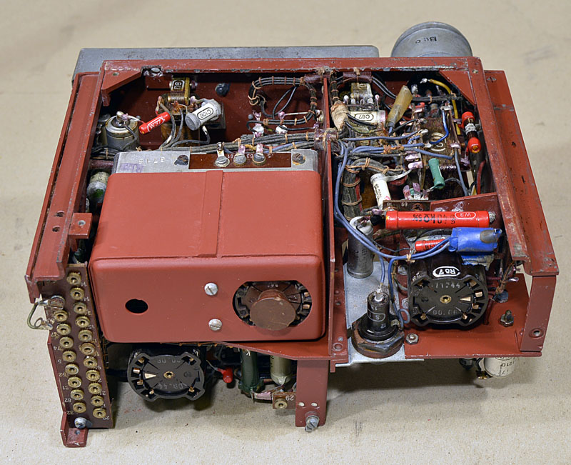
Behind the front plate. Look at the amazing mechanics.
Everything is cleaned and adjusted and ready for years of
communication.
Nice ?
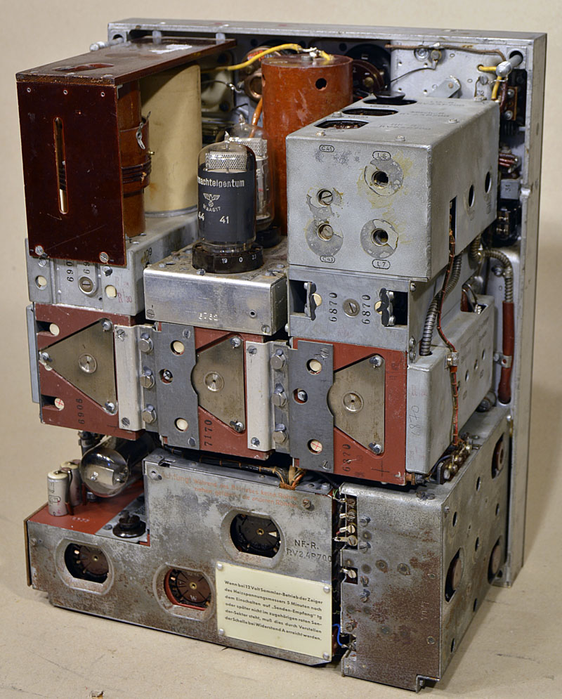
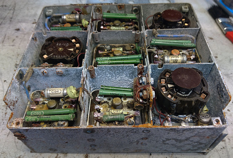
Here is the bottom sections removed. Here we see the variable
capacitors.
From the left is Rx capacitor, Antenna tuner, Tx capacitor.
..........................................................................................................
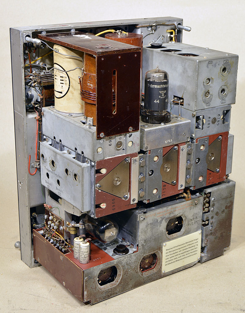
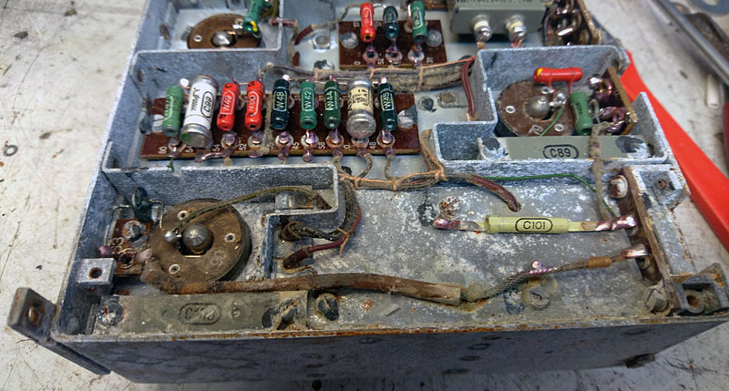
LF SECTION
Power and LF section.
| Here we see three RV12P2000 tubes. From the left we have Microphone Amplifier / CW side tone oscillator, BFO and LF audio amplifier. |
Here the covers are removed.
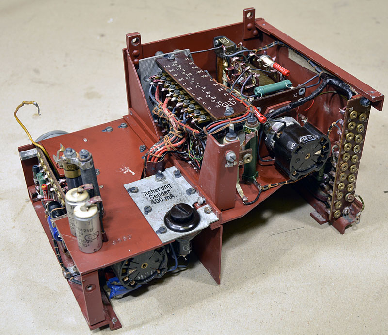
Here is the large power switch that chooses between power OFF,
AM, CW, Tx and Rx. .
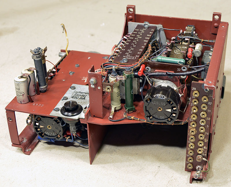
All cable connectors are 3mm screws. They are very well marked
with the net number.
..................................................................................
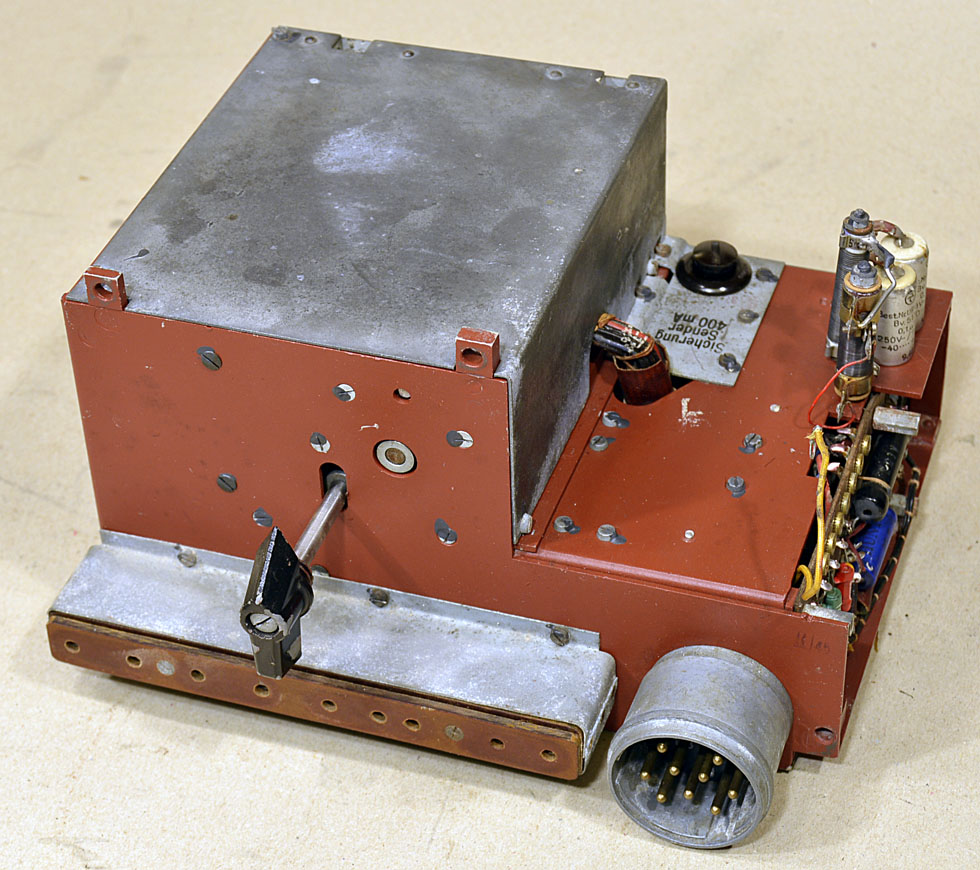
BFO
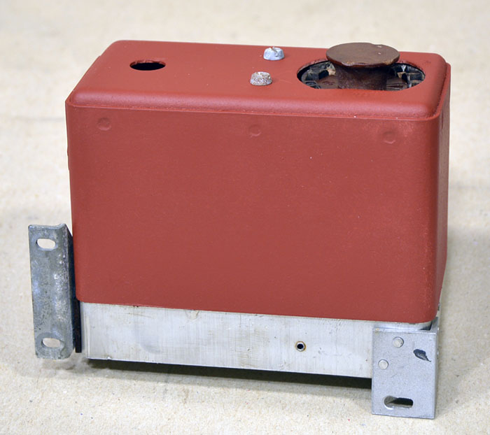
The BFO section was also
water-damaged.
Here is the result of the restoration.
The BFO section is mounted in a beautiful shielded box.
To the right we see the coil and
capacitors.
To the left is the tube RV12P2000
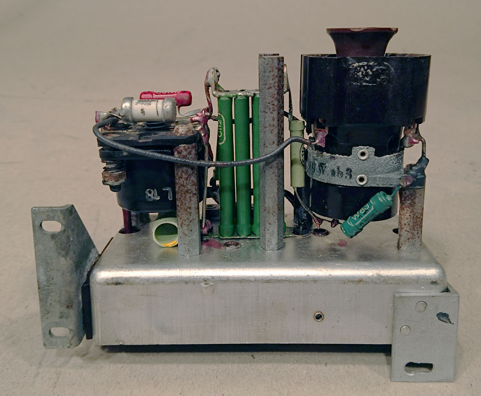
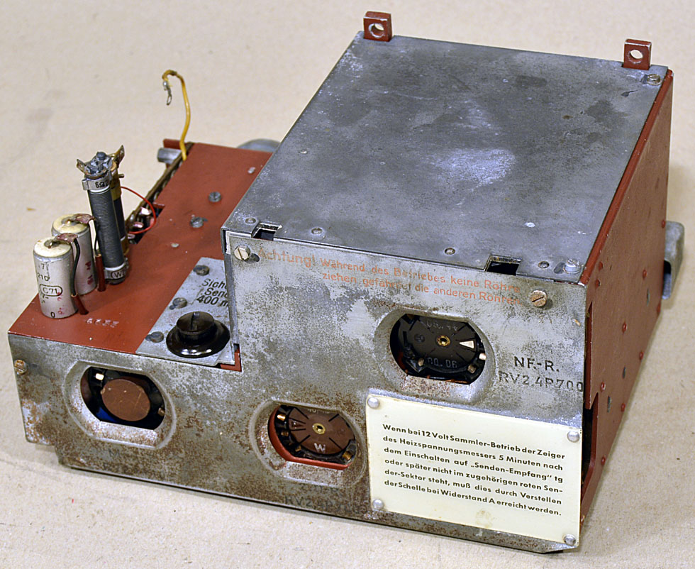
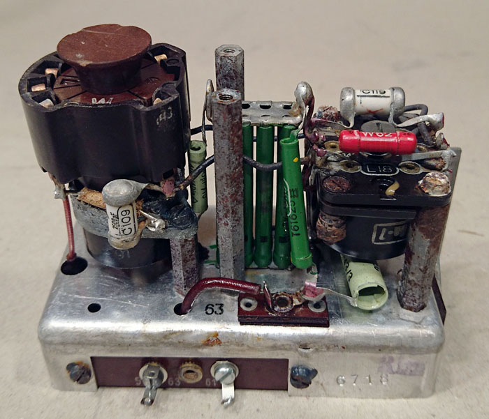
Viewed from the other side.
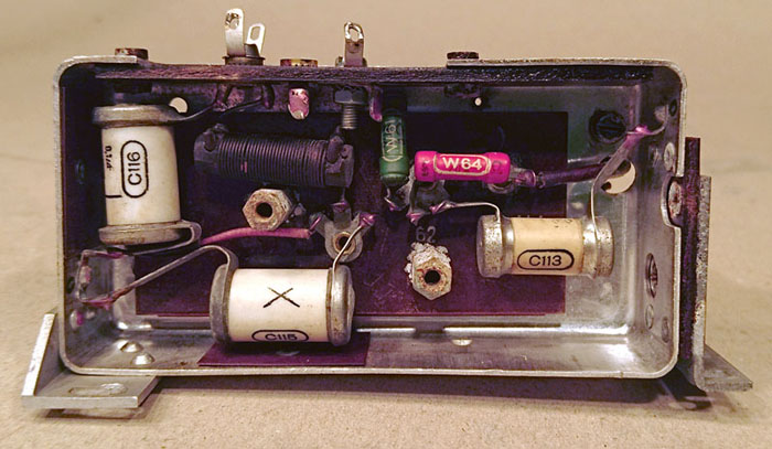
Seen from the bottom. Look at the amazingly beautiful markings on
the capacitors.
IF section before restoration started. Despite the water damage,
everything still works.
I cleaned and trimmed the coils and everything was fine.
The underside of the IF section.
POWERCONNECTOR
| 1 | NC |
| 2 | - 100 Volt RX power,RX bias |
| 3 | power relay output, 2.4V |
| 4 | + 100 Volt RX power, xx mA |
| 5 | + 350 Volt TX power, 200 mA |
| 6 | + 4.8 Volt TX heater, 1.7 A |
| 7 | + XX Volt, Key relay |
| 8 | + 2.4 Volt, RX heater, 0.6 A |
| 9 | GND, -2.4V, -4.8V, -350V |
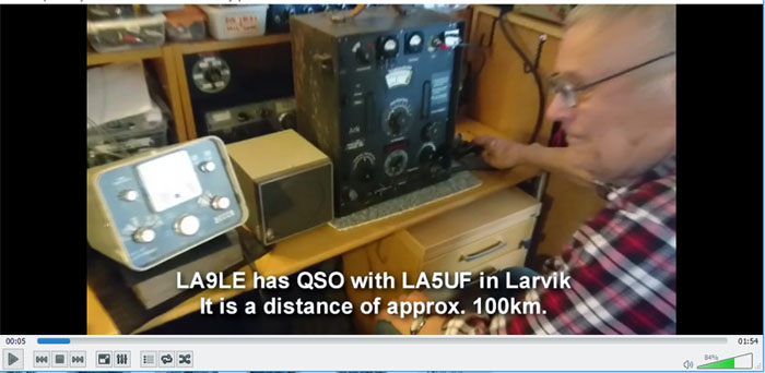
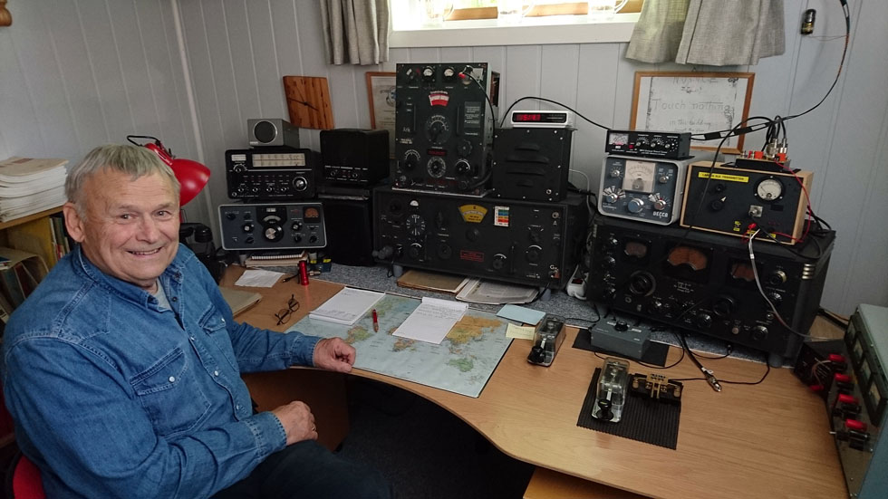
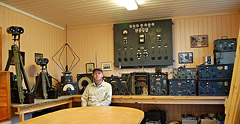
LA9LE has built a new shack with old equipment.
He operates 15W.S.E.b daily.
He often calls on 3570 kHz