 |
LA6NCA RF PROBE. |
 |
|
LA6NCA RF PROBE. |
|
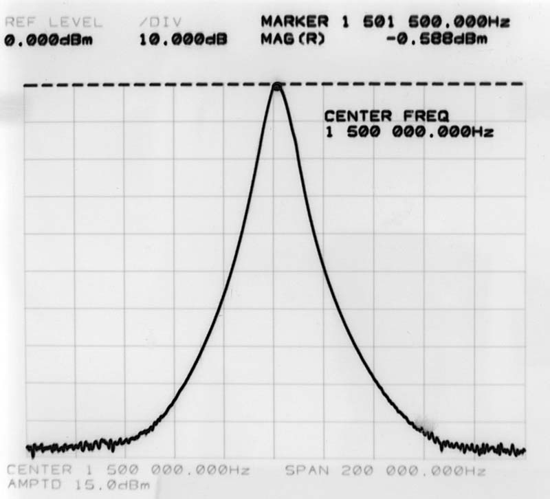
| This is the frequency response curve for the MF
filter in a E10K receiver. Look at the great dynamic range. 100 dB from top to bottom of the curve !! This curve is measured with my new HF-probe and a HP network analyzer. |
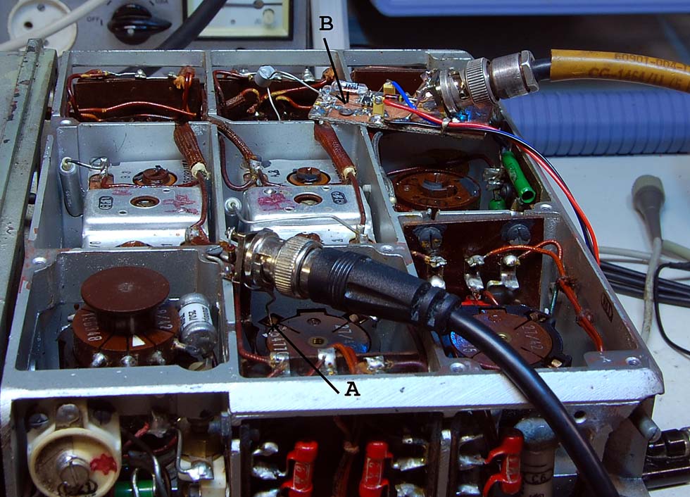
| "A" is the input signal
from the network analyzer. This signal is terminated in a 50 ohm resistor. The signal is then connected to the RF-mixers anode though a small capacitor and a 47K resistor. “B” is the input signal from the MF filter output. I use here a 0.1 pF serial capacitor. This will not interfere with the MF signal. |
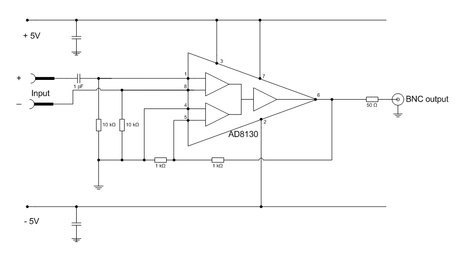
| My new HF-probe is designed with a new type OPAMP.
AD8130. This is an opamp with separate feedback terminals. The input signals are balanced and have very high input impedance. The + input capacitor can be 0.1 to 1 pF. This will not interfere with the radio signal in the circuit. The – input signal shall be connected to GND near the measuring point. The output signal is serial terminated with a 50 ohm resistor. This because we want flat frequency response from 1 MHz to 200 MHz. The two 1K resistors give the amplifier a gain of two to compensate the loss in the serial terminated resistor. |
BACK TO LA6NCA HOMEBREW MAIN PAGE